Envelope tracking power transmitter using common-gate voltage modulation linearizer

a technology of voltage modulation and envelope tracking power transmitter, which is applied in the direction of amplifiers with semiconductor devices/discharge tubes, amplifier modifications to reduce non-linear distortion, rf amplifiers, etc., can solve the problems of reducing the overall efficiency of the power amplifier, the implementation of real-time feed-back circuit that reprocesses signals in digital domain and outputs the processed signal inefficient, and the difficulty of envelope tracking power transmitters to be integrated with other circuitry of the transmitter

Inactive Publication Date: 2015-04-02
KOREA ADVANCED INST OF SCI & TECH
View PDF1 Cites 32 Cited by
  • Summary
  • Abstract
  • Description
  • Claims
  • Application Information

AI Technical Summary

Benefits of technology

[0017]Accordingly, the envelope tracking power transmitter may maintain output capacitance by increasing the common gate bias voltage applied to gates of the common-gate transistors and may improve AM-to-AM characteristic and AM-to-PM characteristic.

Problems solved by technology

A power amplifier in the transmitter may maintain linearity of a signal by operating in a back-off area to an extent of the PAPR at a maximum output power, however, an output is rapidly decreased in the back-off area to degrade overall efficiency of the power amplifier.
As for base stations, for implementing the DPD scheme, additional feed-back circuits are required and implementation of real-time feed-back circuit that reprocesses signals in digital domain and outputs the processed signal is not efficient.
In addition, for increasing efficiency, envelope tracking power transmitters have been developed, however, the envelope tracking power transmitters are difficult to be integrated with other circuitry of the transmitter because the envelope tracking power transmitters use hetero junction bipolar transistor (HBT) compound semiconductors and SiGe BiCMOS semiconductors.

Method used


Image

  • Envelope tracking power transmitter using common-gate voltage modulation linearizer
  • Envelope tracking power transmitter using common-gate voltage modulation linearizer
  • Envelope tracking power transmitter using common-gate voltage modulation linearizer

Examples


Embodiment Construction

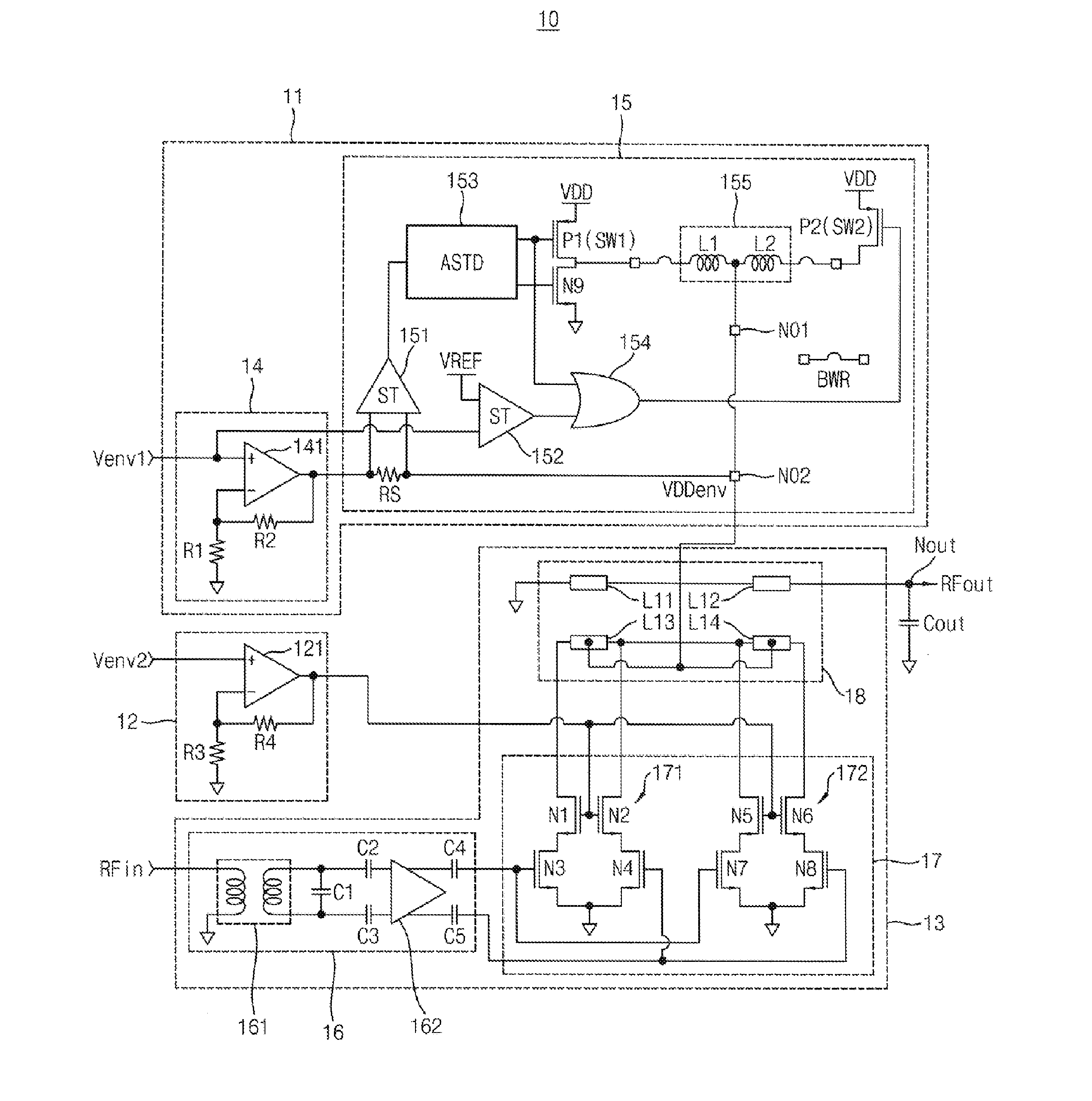
[0026]Various example embodiments will be described more fully hereinafter with reference to the accompanying drawings, in which some example embodiments are shown. The present inventive concept may, however, be embodied in many different forms and should not be construed as limited to the example embodiments set forth herein. Rather, these example embodiments are provided so that this disclosure will be thorough and complete, and will fully convey the scope of the present inventive concept to those skilled in the art. In the drawings, the sizes and relative sizes of layers and regions may be exaggerated for clarity. Like numerals refer to like elements throughout.

[0027]It will be understood that, although the terms first, second, third etc. may be used herein to describe various elements, these elements should not be limited by these terms. These terms are used to distinguish one element from another. Thus, a first element discussed below could be termed a second element without de...


PUM


Abstract

An envelope tracking power transmitter includes an envelope amplifier, a common-gate power modulation linearizer and a power amplifier. The envelope amplifier may receive a first envelope voltage to generate a power supply voltage that is amplified in proportion to change of the first envelope voltage. The common-gate power modulation linearizer may receive a second envelope voltage to amplify the second envelope voltage according to change of the second envelop voltage. The power amplifier may receive a first output of the envelope amplifier as a power supply voltage and a drain bias voltage, may receive a second output of the common-gate power modulation linearizer as a common gate bias voltage, and may amplify a radio frequency (RF) input signal to provide a RF output signal by maintaining an output capacitance according to an envelope of the RF input signal.

Description

CROSS-REFERENCE TO RELATED APPLICATION[0001]This application claims priority under 35 U.S.C. §119 to Korean Patent Application No. 10-2013-0117154, filed on Oct. 1, 2013, in the Korean Intellectual Property Office (KIPO), the contents of which are herein incorporated by reference in their entirety.BACKGROUND[0002]1. Technical Field[0003]Example embodiments relate generally to envelope tracking power transmitters and more particularly to envelope tracking power transmitters using common-gate voltage modulation linearizer.[0004]2. Description of the Related Art[0005]Conventional transmitters use modulation schemes such as quadrature amplitude modulation (QAM) scheme or orthogonal frequency division multiplexing (OFDM) scheme for increasing efficiency of bandwidth. Since modulated signals have non-constant envelope, peak-to-average power ratio (PAPR) of the modulated signals is increased. A power amplifier in the transmitter may maintain linearity of a signal by operating in a back-off...

Claims


Application Information

Patent Timeline
Patent Type & Authority Applications(United States)
IPC IPC(8): H03F1/02H03F3/193H03F3/45H03F3/217
CPCH03F1/0222H03F3/2178H03F3/193H03F2203/45031H03F2200/451H03F2200/102H03F2203/211H03F3/45179H03F3/2173H03F3/245H03F3/45183H03F3/45188H03F3/45475H03F3/604H03F2200/432H03F2203/45302H03F2203/45731H03F1/32
Inventor PARK, CHUL SOONKIM, WOO YOUNGOH, INN YEALJANG, JOO YOUNGSON, HYUK SU
Owner KOREA ADVANCED INST OF SCI & TECH
Why Eureka
Try Eureka