Portable device for detecting molecule(s)

a technology for detecting molecules and devices, applied in biochemistry apparatuses, biochemical equipment and processes, component separation, etc., can solve the problems of reducing affecting the optical path, and affecting the accuracy of detection,

Active Publication Date: 2015-04-23
UBIQUITOME LTD
View PDF4 Cites 41 Cited by
  • Summary
  • Abstract
  • Description
  • Claims
  • Application Information

AI Technical Summary

Benefits of technology

[0022]In an embodiment, the optical assembly further comprises an attenuator for reducing the power of the excitation beam from the collimator. In a further embodiment, the attenuator comprises a neutral density (ND) filter. In a further embodiment, the attenuator reduces the power of the excitation beam by a factor of about 10. In a further embodiment, the attenuator is positioned between the collimator and the beam splitter arrangement. In a further embodiment, about 10 mW is incident on the ND filter, and about 1 mW exits the ND filter to the beam splitter arrangement. In an alternative embodiment, the optical assembly may comprise at least one attenuator for reducing the power of at least one of the plurality of split excitation beams from the beam splitter arrangement.
[0023]In an embodiment, the optical assembly further comprises a wavelength filter for filtering any spectral components in the excitation beam from the collimator that fall within a band of the reaction light from the sample in at least one of t

Problems solved by technology

The evaporation and condensation of the sample mixture on the cover of the reaction vessel interferes with the optical path of the radiation beam into the reaction vessel and of the fluorescence from the sample within the reaction vessel.
The optical interference and changes to assay performance reduces the accuracy of the detection.
As a result, these apparatuses are generally relatively large, heavy, and inefficient in terms of power use, in particular when analysing only a small number of samples.
These apparatuses are also commonly expensive and/or complex.
An object with a low thermal mass has a low heat capacity or low specific heat capacity, and requires little heat to increase the temperature of the object.
Widely differing signals from identical samples is not desirable.
Secondly, photo bleaching effects of the sample (if present) will vary among otherwise identical samples due to variation in incident laser power thereby compromising the quality of the gathered data further.
Howe

Method used


Image

  • Portable device for detecting molecule(s)
  • Portable device for detecting molecule(s)
  • Portable device for detecting molecule(s)

Examples


first example embodiments

of the Device

The Reaction Vessel Holder

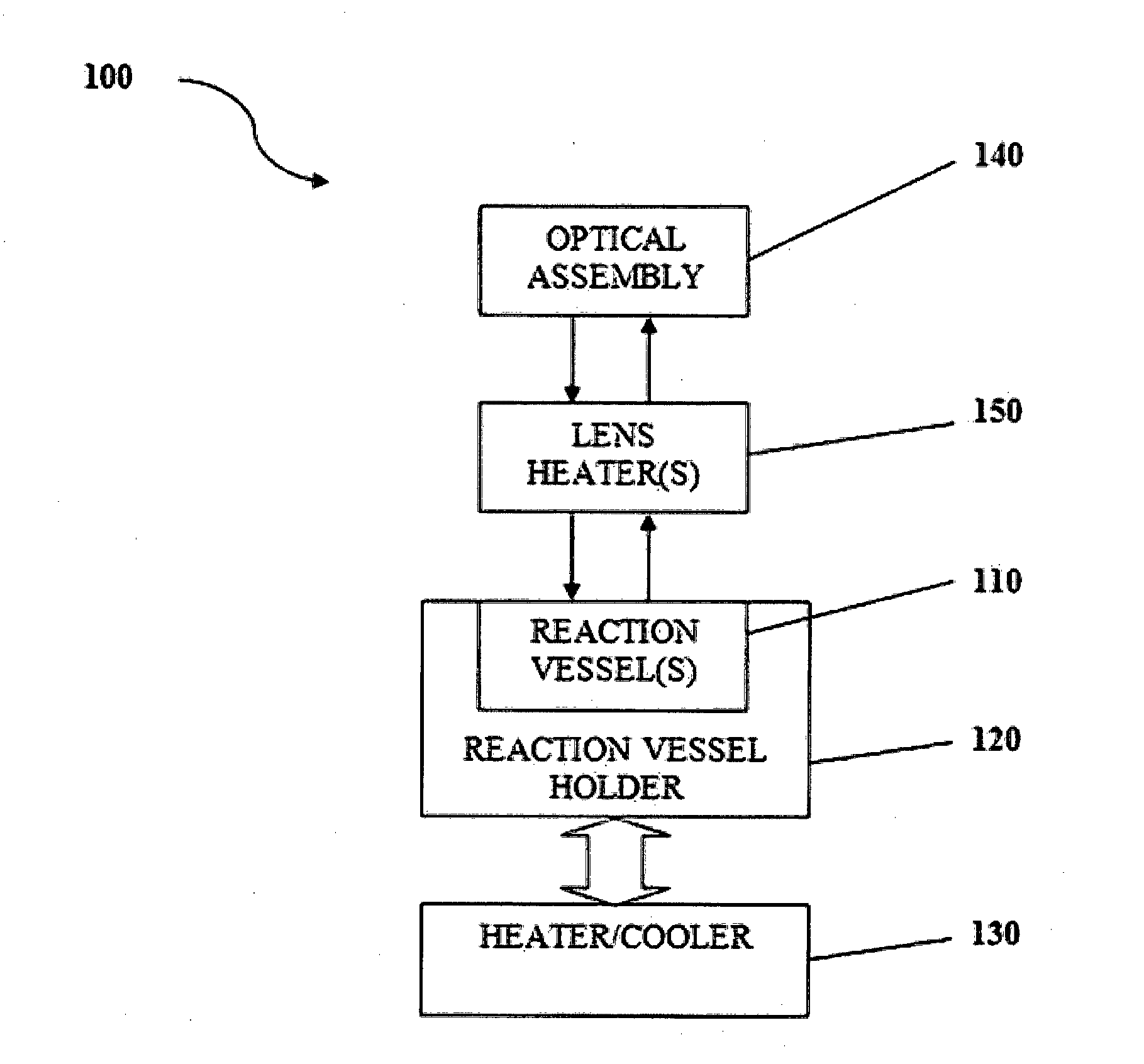
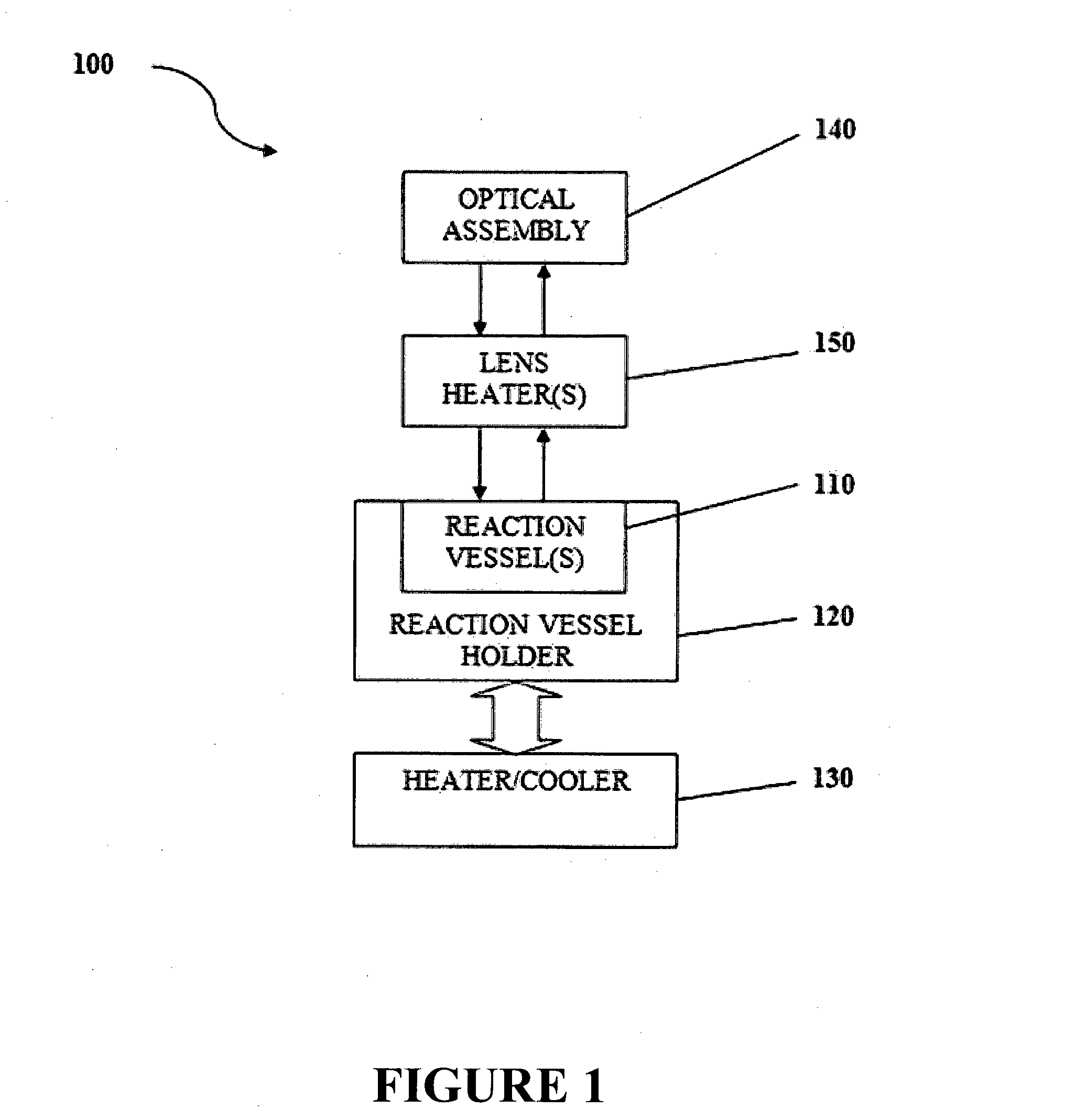
[0245]Referring to FIG. 13, the device comprises a lower casing 80′. The lower casing 80′ houses the reaction vessel holder 120′ and the heater / cooler 130′. The reaction vessel holder 120′ comprises four vessel receptacles 121′, each vessel receptacle being arranged to receive a respective one of the reaction vessels.

[0246]The reaction vessels holder 120′ comprises a housing 122′ which houses the vessel receptacles 121′ and an insulative material 123′ such as aerogel or any other suitable materials described above (or alternatively an air gap) which substantially fills the space between the vessel receptacles 121′ and the housing 122′.

The Heater / Cooler

[0247]Referring again to FIG. 13, the heater / cooler 130′ comprises three TEC devices 131′, two of which are shown in FIG. 13. The TEC devices 131′ are thermally coupled to four vessel receptacles 121′.

[0248]The TEC devices 131′ physically contact a plate 132′ made of a substantially thermally cond...

second example embodiments

of the Device

The Reaction Vessel Holder

[0278]FIG. 24 shows the reaction vessel holder 120″ for the reaction vessel of the second example embodiments of the invention. The reaction holder 120″ is in the form of a cassette housing 121″ that comprises one or more reaction chambers 110″ that can be closed. In the embodiment shown, the reaction vessel holder 120″ comprises eighteen reaction chambers 110″ that are integral with the reaction vessel holder 120″. As previously described, the reaction vessels 110″ may alternatively be removable from the reaction vessel holder 120″.

[0279]The or each reaction chamber 110″ has a low volume and is configured to receive a sample for molecule detection. By having no air gap above the reaction mixture, the need for lens heaters is eliminated. The housing 121″ may be disposable. The reaction vessel holder 120″ is optically transparent on bottom side and on a top side to allow an excitation light to enter the reaction chamber 110″ from the top or bott...

third example embodiments

of the Device

[0307]The third example embodiments of the device are substantially similar to the second example embodiments of the device. One of the differences between the two example embodiments is the beam splitter arrangement. According to the third example embodiments, the secondary tiers in the beam splitter arrangement of the second example embodiments are not present.

[0308]Referring to FIG. 34, the beam splitter arrangement 620′ is configured to split the excitation beam into up to k number of split excitation beams, k being an even integer greater than two, wherein the beam splitters 621a′″-621k′″ are arranged in m number of tiers 623a′-f′″, where m is an integer greater than 1 and k=2×m. A first tier 623a′″ contains one beam splitter 621a′″ that is configured to receive the excitation beam from an excitation arrangement, and to split the incoming beam into two split excitation beams. An ith tier 623b′″-f′″, i being an integer ranging from 2 to m, is configured to receive i...


PUM

PropertyMeasurementUnit
Fractionaaaaaaaaaa
Fractionaaaaaaaaaa
Wavelengthaaaaaaaaaa

Abstract

An optical assembly 140 for a portable device for detecting molecule(s) within reaction vessels 110 comprises a collimator 403, a beam splitter arrangement and a plurality of guide arrangements 143. The collimator 403 collimates an excitation beam from an excitation source 400. The beam splitter arrangement splits the excitation beam from the collimator into a plurality of split excitation beams. Each beam splitter splits an incoming beam into two beams. In the case where the beam splitter arrangement comprises more than one beam splitter, the beam splitters are arranged in tiers such that a first tier comprises one beam splitter for receiving the excitation beam from the collimator, and each of the other tiers comprises one or more beam splitters. Each beam splitter in at least one of the other tiers receives a split excitation beam from a previous tier. Each guide arrangement 140 guides a respective one of the plurality of split excitation beams along an excitation path A from the beam splitter arrangement into a reaction vessel 110 containing a sample to stimulate an emission of a reaction light from the sample. Each guide arrangement 140 further guides reaction light from the sample along a detection path B towards a detector arrangement 142.

Description

FIELD OF THE INVENTION[0001]The present invention relates to a portable device for detecting molecule(s). In preferred embodiments, the device may be used for one or more of: amplification and detection of nucleic acids including analysis of polymerase chain reactions (such as quantitative polymerase chain reactions), protein analysis, ligand analysis, or fluorescence analysis of any chemical reactions, for example.BACKGROUND[0002]Systems and methods for detecting molecule(s) are widely known and used.[0003]Amplification of nucleic acids can be performed using quantitative polymerase chain reaction (Q-PCR) analysis for example. Generally for a Q-PCR analysis, the temperature of a sample within a reaction vessel is repeatedly cycled between a higher temperature at which the template DNA is denatured, and a lower temperature at which the primers in the sample anneal to a targeted DNA sequence and the DNA replicates. This thermal cycling is commonly repeated up to 40 times until the DN...

Claims


Application Information

Patent Timeline
IPC IPC(8): G01N21/64B01L9/06C12Q1/70C12Q1/68B01L7/00
CPCG01N21/6452G01N21/6486C12Q1/686B01L7/52C12Q1/701B01L2300/0654B01L9/06G01N2201/0612G01N2021/6463G01N2201/068C12Q1/689G01N2021/6419G01N2021/6421G01N2201/0221G02B27/146G01N21/0332G01N2021/158
Inventor RAWLE, CHRISTOPHER BRUCE
Owner UBIQUITOME LTD
Why Eureka
Try Eureka