Catalytically heated fuel processor with replaceable structured supports bearing catalyst for fuel cell

Active Publication Date: 2015-04-30
HELBIO
View PDF4 Cites 2 Cited by
  • Summary
  • Abstract
  • Description
  • Claims
  • Application Information

AI Technical Summary

Benefits of technology

[0019]As another feature, the integrated combustor/steam reformer assembly includes two rectangular sections defined by steel plates in heat transfer relation to each other, as described above. In this case, fuel and steam mixture is supplied to one of the rectangular sections which contain reforming catalyst coated on corrugated fecralloy sheets which induces reforming reactions. A fuel and air mixture is supplied to the other rectangular passage which contains fecralloy sheets coated with suitable catalyst which promotes combustion reactions. With the use of suitably placed buffles (rectangular steel sticks) the fuel and air mixture passage forms an “S” shape. Steel strips placed suitably in the perimeter of the rectangular plate restrict flow to the desired direction and shape.
[0020]In another aspect of the invention the integrated combustor/steam reformer assembly includes a multitude of tubular sections defined by concentrically placed cylindrical walls separated from each other and supported on plates machined as to allow some of the cylindrical walls to pass through them and to be in fluid connection with only one side of the plate. One flow passage which passes t

Problems solved by technology

The reason is that the technology for large scale hydrogen production can not be easily downscaled.
The problem lies in the low energy density of hydrogen which makes its transportation very inefficient and expensive.
Transporting hydrogen in compressed or liquid form requires specialized and bulky equipment.
This minimizes the amount of hydrogen which can be safely carried, increasing resource consumption and cost.
This is a rather inefficient arrangement since the hydrogen producing reforming reaction forms a small part of overall reactor.
Materials limitations also dictate the avoidance of extremely high temperatures (>1000° C.) for the reforming reactor tubes, further limiting the ability to place the combustion burners in close proximity to the reforming tubes.
All these mean that traditional steam methane reforming reactor configurations are very large and new configurati

Method used


Image

  • Catalytically heated fuel processor with replaceable structured supports bearing catalyst for fuel cell
  • Catalytically heated fuel processor with replaceable structured supports bearing catalyst for fuel cell
  • Catalytically heated fuel processor with replaceable structured supports bearing catalyst for fuel cell

Examples


Embodiment Construction

[0030]The present invention is described in detail with reference to a few preferred embodiments illustrated in the accompanying drawings. The description presents numerous specific details included to provide a thorough understanding of the present invention. It will be apparent, however, to one skilled in the art that the present invention can be practiced without some or all of these specific details. On the other hand, well known process steps, procedures and structures are not described in detail as to not unnecessarily obscure the present invention.

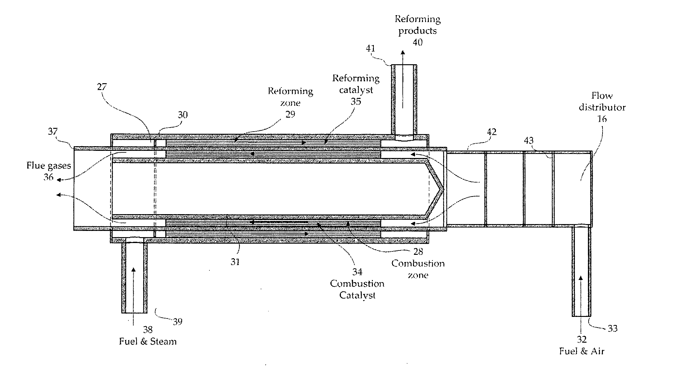
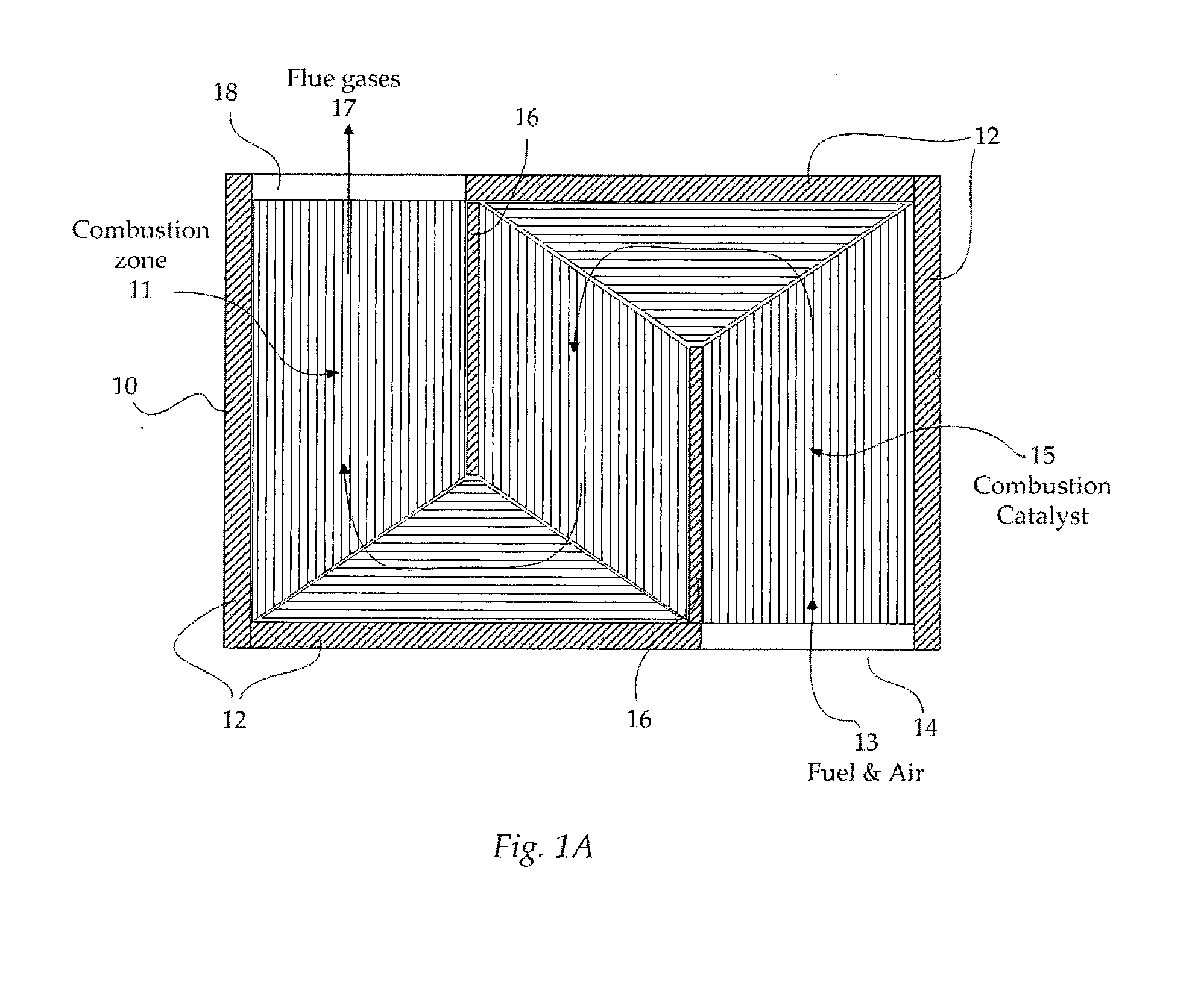
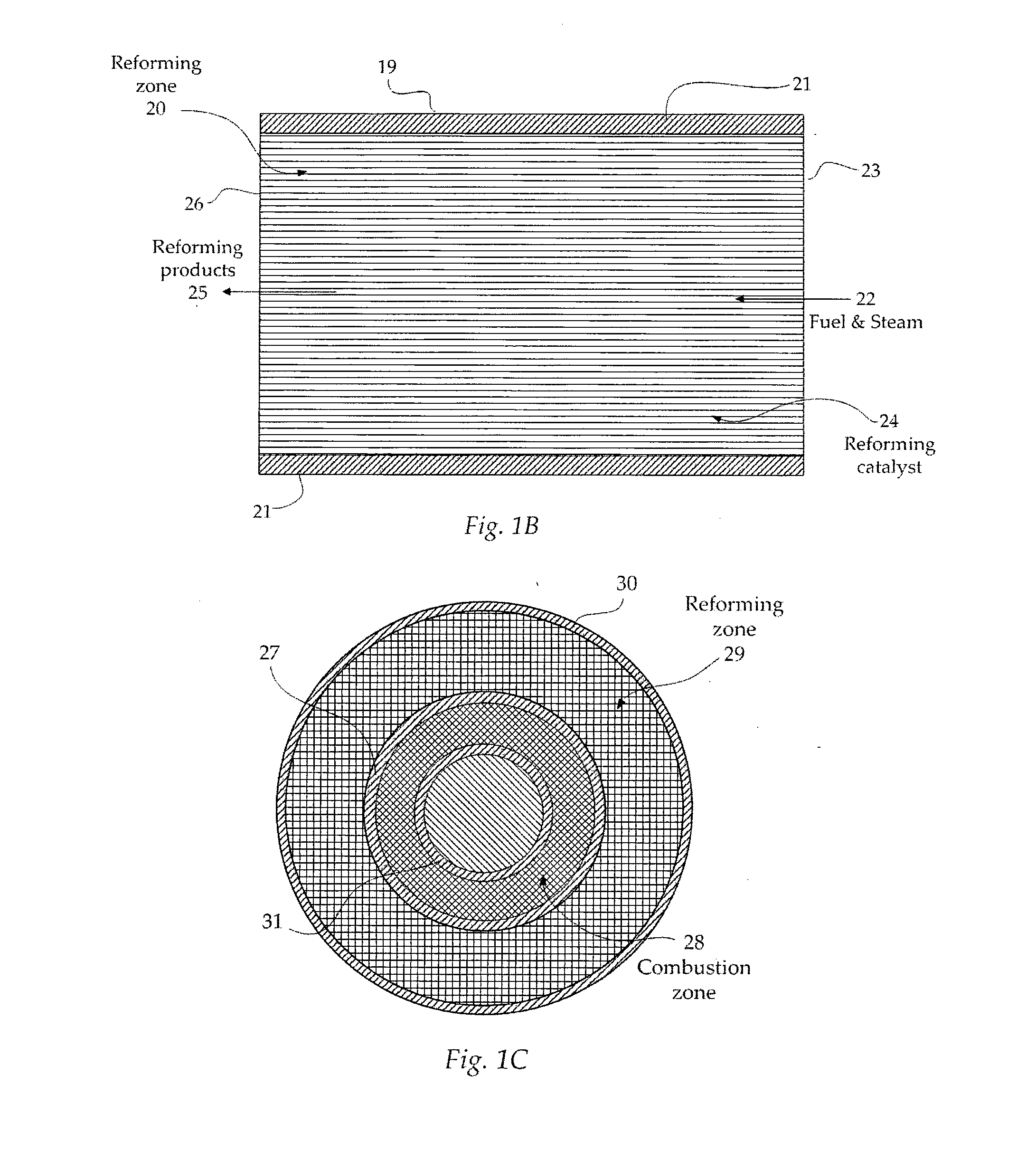
[0031]FIG. 1A illustrates the “S” shape flow passage of the combustion zone of a plate-type reformer according to one embodiment of the present invention. The combustion flow passage assembly includes a plate 10 that separates the combustion zone 11 from the reforming zone. The steel strips 12 placed suitably in the perimeter of the rectangular plate restrict flow to the desired direction and act as the reactor wall. A fuel and air ...


PUM


Abstract

A highly compact heat integrated fuel processor, which can be used for the production of hydrogen from a fuel source, suitable to feed a fuel cell, is described. The fuel processor assembly comprises a catalytic reforming zone (29) and a catalytic combustion zone (28), separated by a wall (27). Catalyst able to induce the reforming reactions is placed in the reforming zone and catalyst able to induce the combustion reaction is placed in the combustion zone, both in the form of coating on a suitable structured substrate, in the form of a metal monolith. Fe—Cr—Al—Y steel foils, in corrugated form so as to enhance the available area for reaction, can be used as suitable substrates. The reforming and the combustion zones can be either in rectangular shape, forming a stack with alternating combustion/reforming zones or in cylindrical shape forming annular sections with alternating combustion/reforming zones, in close contact to each other. The close placement of the combustion and reforming catalyst facilitate efficient heat transfer through the wall which separates the reforming and combustion chambers.

Description

FIELD OF THE INVENTION[0001]This invention relates to very compact fuel processor assemblies where hydrocarbons or oxygenates are reformed to produce a hydrogen rich stream which can be fed to a fuel cell for electrical and thermal energy production.BACKGROUND OF THE INVENTION[0002]The use of hydrogen as an alternative energy vector is progressing along the road to implementation. The use of hydrogen in fuel cells to produce electricity or to co-generate heat and electricity, represents the most environmentally friendly energy production process due to the absence of any pollutant emissions. Most importantly, hydrogen can be produced from renewable energy sources, such as biofuels, alleviating concerns over the long-term availability of fossil fuels and energy supply security.[0003]Large scale production of hydrogen is well understood and widely practiced in refineries and chemical plants—particularly in the ammonia production industry. For industrial applications requiring smaller ...

Claims


Application Information

Patent Timeline
IPC IPC(8): B01J8/02C01B3/38C01B3/32
CPCB01J8/0285C01B3/323C01B3/384B01J2208/02C01B2203/107C01B2203/0811C01B2203/1035C01B2203/1082C01B2203/0233H01M8/06B01J19/249B01J2219/2453B01J2219/2454B01J2219/2458B01J2219/2459B01J2219/2465B01J2219/247B01J2219/2479B01J2219/2485C01B2203/1005C01B2203/1047C01B2203/1229C01B2203/1241Y02E60/50
Inventor VERYKIOS, XENOPHONHALKIDES, THOMASSTAVRAKAS, ANDREASBASAYIANNIS, ARIS
Owner HELBIO
Why Eureka
Try Eureka