
Bright and Durable Field Emission Source Derived from Refractory Taylor Cones

a taylor cone and emission source technology, applied in the manufacture of electrode systems, electric discharge tubes/lamps, instruments, etc., can solve the problems of general undesirable, more problematic materials that form solid oxides, etc., and achieve the effect of economical operation and reliable and cost-effective production

Active Publication Date: 2015-05-07
HIRSCH GREGORY
View PDF14 Cites 10 Cited by
  • Summary
  • Abstract
  • Description
  • Claims
  • Application Information

AI Technical Summary

Benefits of technology

The invention is about a new method to create a bright field emitter that can be easily replaced if needed, reducing downtime. The method involves creating a frozen Taylor cone and using it as a field emitter by reversing the electrical potential. The frozen Taylor cone can be used in various applications such as electron microscopy, particle accelerators, and microwave sources. The method allows for the formation of a collimated electron beam and can be integrated with optics for easy inspection and use. The brightness of the field emitter is higher than currently used thermionic emitters, making it suitable for applications requiring higher anode loading. Overall, this invention provides a more efficient and flexible solution for creating a bright field emitter.

Problems solved by technology

Materials that form solid oxides in particular can be more problematic than those that do either do not oxidize, or form volatile oxides that readily evaporate.
The one situation that is generally very undesirable is if a refractory solid oxide thin skin or thicker crust forms on the hot liquid metal.

Method used


Image

  • Bright and Durable Field Emission Source Derived from Refractory Taylor Cones
  • Bright and Durable Field Emission Source Derived from Refractory Taylor Cones
  • Bright and Durable Field Emission Source Derived from Refractory Taylor Cones

Examples


Embodiment Construction

[0060]The figures and the following description relate to preferred embodiments of the present invention by way of illustration only. It should be noted that from the following discussion, alternative embodiments of the structures and methods disclosed herein will be readily recognized as viable alternatives that may be employed without departing from the principles of the claimed invention.

[0061]Reference will now be made in detail to several embodiments of the present invention(s), examples of which are illustrated in the accompanying figures. It is noted that wherever practicable, similar or like reference numbers may be used in the figures and may indicate similar or like functionality. The figures depict embodiments of the present invention for purposes of illustration only. One skilled in the art will readily recognize from the following description that alternative embodiments of the structures and methods illustrated herein may be employed without departing from the principl...


PUM

PropertyMeasurementUnit
melting pointaaaaaaaaaa
heightaaaaaaaaaa
electric fieldaaaaaaaaaa

Abstract

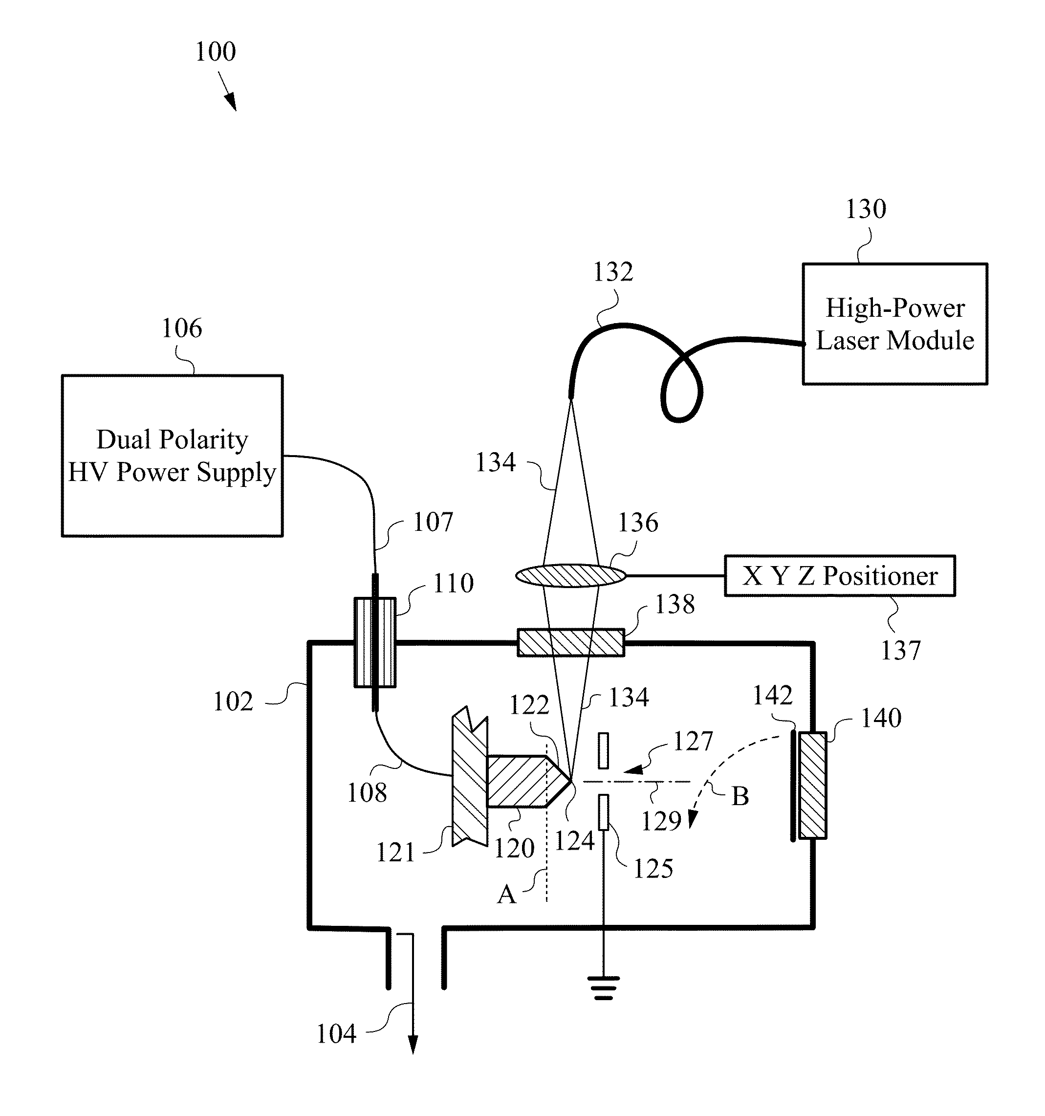
A method of producing field emitters having improved brightness and durability relying on the creation of a liquid Taylor cone from electrically conductive materials having high melting points. The method calls for melting the end of a wire substrate with a focused laser beam, while imposing a high positive potential on the material. The resulting molten Taylor cone is subsequently rapidly quenched by cessation of the laser power. Rapid quenching is facilitated in large part by radiative cooling, resulting in structures having characteristics closely matching that of the original liquid Taylor cone. Frozen Taylor cones thus obtained yield desirable tip end forms for field emission sources in electron beam applications. Regeneration of the frozen Taylor cones in-situ is readily accomplished by repeating the initial formation procedures. The high temperature liquid Taylor cones can also be employed as bright ion sources with chemical elements previously considered impractical to implement.

Description

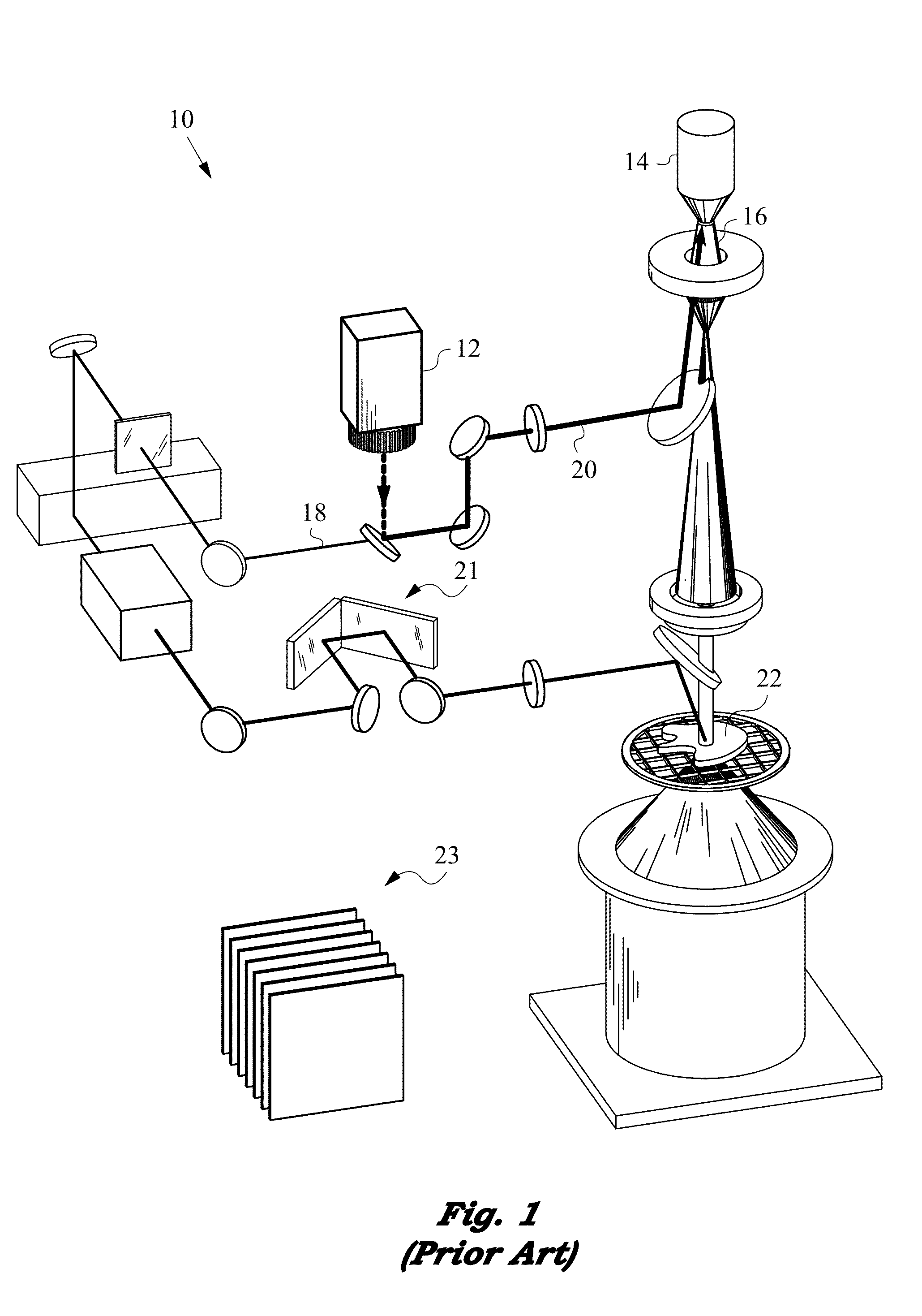
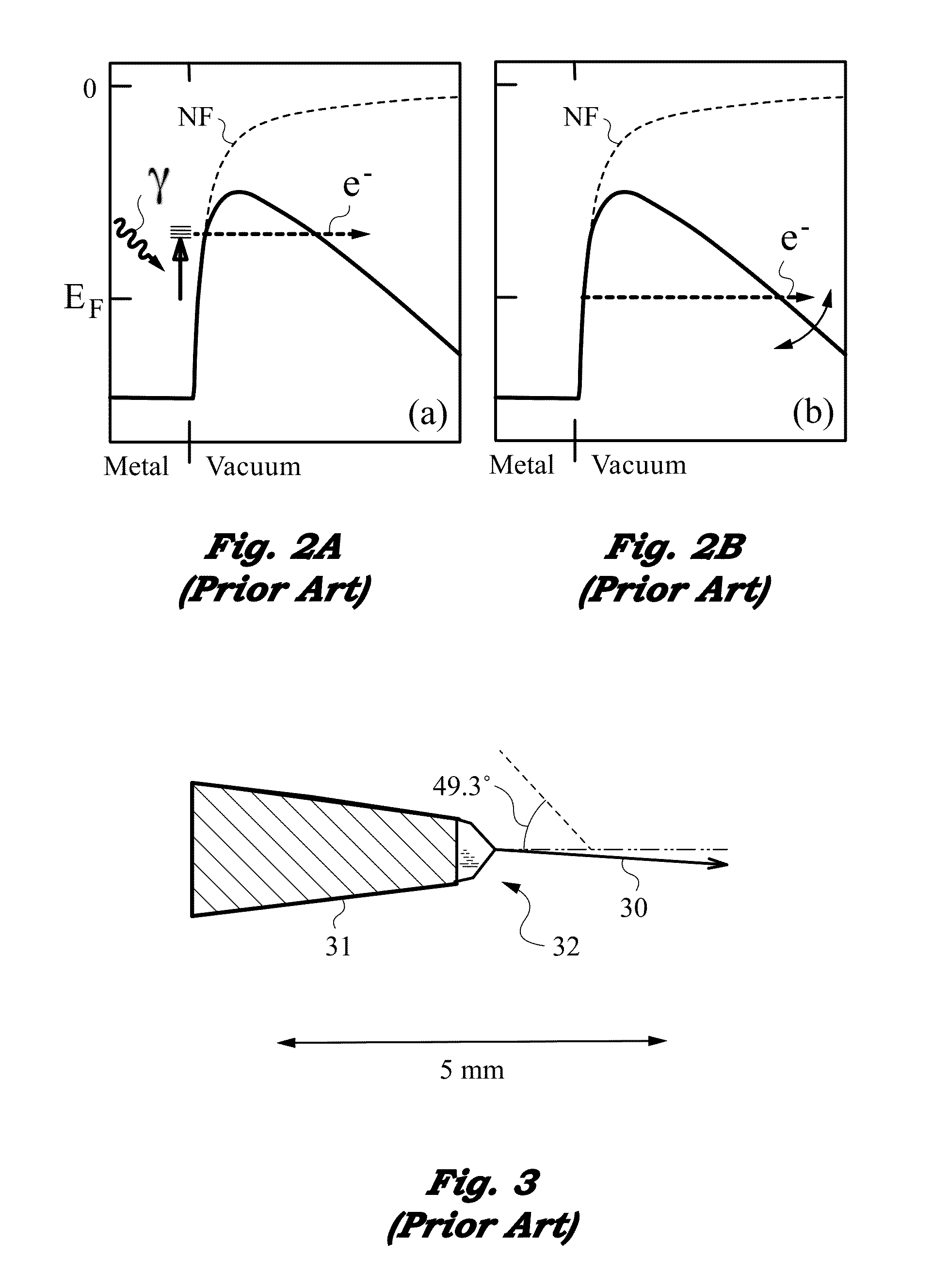
[0001]This application claims priority from U.S. Provisional Patent Application No. 61 / 962,462 filed on Nov. 7, 2013 that is entitled “Bright and Durable Field-Emission Source” and is incorporated herein by reference in its entirety.GOVERNMENT LICENSE RIGHTS[0002]This invention was made with government support under Grant No. DE-SC0011345 awarded by the Department of Energy on Feb. 18, 2014.FIELD OF THE INVENTION[0003]This invention relates generally to providing a bright source of charged particles based on the formation of high-temperature Taylor cones. In particular the invention teaches the creation of a bright and durable source of electrons by field emission for use in a variety of electron beam applications, such as electron microscopy, particle accelerators, x-ray sources, and microwave sources.BACKGROUNDPrior ArtField Emission[0004]Achieving a reliable and extremely bright source of electrons for applications in the technical area of electron beam (e-beam) instrumentation i...

Claims


Application Information

Patent Timeline
Patent Type & Authority Applications(United States)
IPC IPC(8): G21K5/02
CPCG21K5/02H01J37/08H01J2237/0805H01J1/3044H01J9/025H01J2201/30411H01J2237/06341H01J37/073H01J1/304
Inventor HIRSCH, GREGORY
Owner HIRSCH GREGORY
Learn More