Quantum cascade detector

a detector and quantum cascade technology, applied in the field of quantum cascade detectors, can solve the problems of low sensitivity, low photodetection sensitivity, and carrier transport still in an inefficient state, and achieve the effect of improving the photodetection sensitivity to incident ligh

Active Publication Date: 2015-05-07
HAMAMATSU PHOTONICS KK
View PDF0 Cites 4 Cited by
  • Summary
  • Abstract
  • Description
  • Claims
  • Application Information

AI Technical Summary

Benefits of technology

[0015]With this configuration, electron transition according to light absorption from the detection lower level to the detection upper level becomes a transition (diagonal transition) between levels whose centers of wave functions are spatially separated from each other since the detection upper level is a coupled level between two well layers. Accordingly, the carrier lifetime at the detection upper level is lengthened, and relaxation of electrons excited to the detection upper level by light absorption to the detection lower level and generation of a reverse current caused by the relaxation can be suppressed.
[0016]Further, in the above-described quantum cascade detector, the energy interval between the detection lower level and the detection upper level to be used for light absorption is set to be larger than the energy ELO of longitudinal optical (LO) phonons. With this configuration, in the transport level structure for electrons consisting of the third level to the n-th level caused by the third well layer to the n-th well layer in the transport region, high-speed relaxation of electrons by LO phonon scattering can be used. In this case, electrons excited to the detection upper level by light absorption move to the third level in the transport region due to the resonant tunneling effect, and are further transported at a high speed to the detection lower level in the unit laminate structure of the subsequent stage through an electron transport process including high-speed relaxation using LO phonon scattering in the transport level structure consisting of the third level to the n-th level. Accordingly, in the quantum cascade detector constituted as described above, photodetection sensitivity to incident light can be improved.

Problems solved by technology

However, photodetection sensitivity in this case remains at a low level compared with sensitivities of the conventional photodetectors.
A possible cause of this low sensitivity is that, in an existing quantum cascade detector, carrier transport is still in an inefficient state due to, for example, a reverse current generated at a high speed by longitudinal optical (LO) phonon scattering, etc.
That is, it is supposed that, in a quantum cascade detector having the conventional structure, electrons excited to an excitation level (detection upper level) by light absorption from a ground level (detection lower level) in the absorption well layer are not taken out as a current but are relaxed in the reverse direction to the detection lower level by LO phonon scattering, and therefore, sufficient photodetection sensitivity cannot be obtained.

Method used


Image

  • Quantum cascade detector
  • Quantum cascade detector
  • Quantum cascade detector

Examples


Embodiment Construction

[0027]Hereinafter, an embodiment of a quantum cascade detector according to the present invention will be described in detail with reference to the drawings. In the description of the drawings, the same components are attached with the same reference symbols, and overlapping description will be omitted. Moreover, the dimensional ratios in the drawings are not always equal to those in the description.

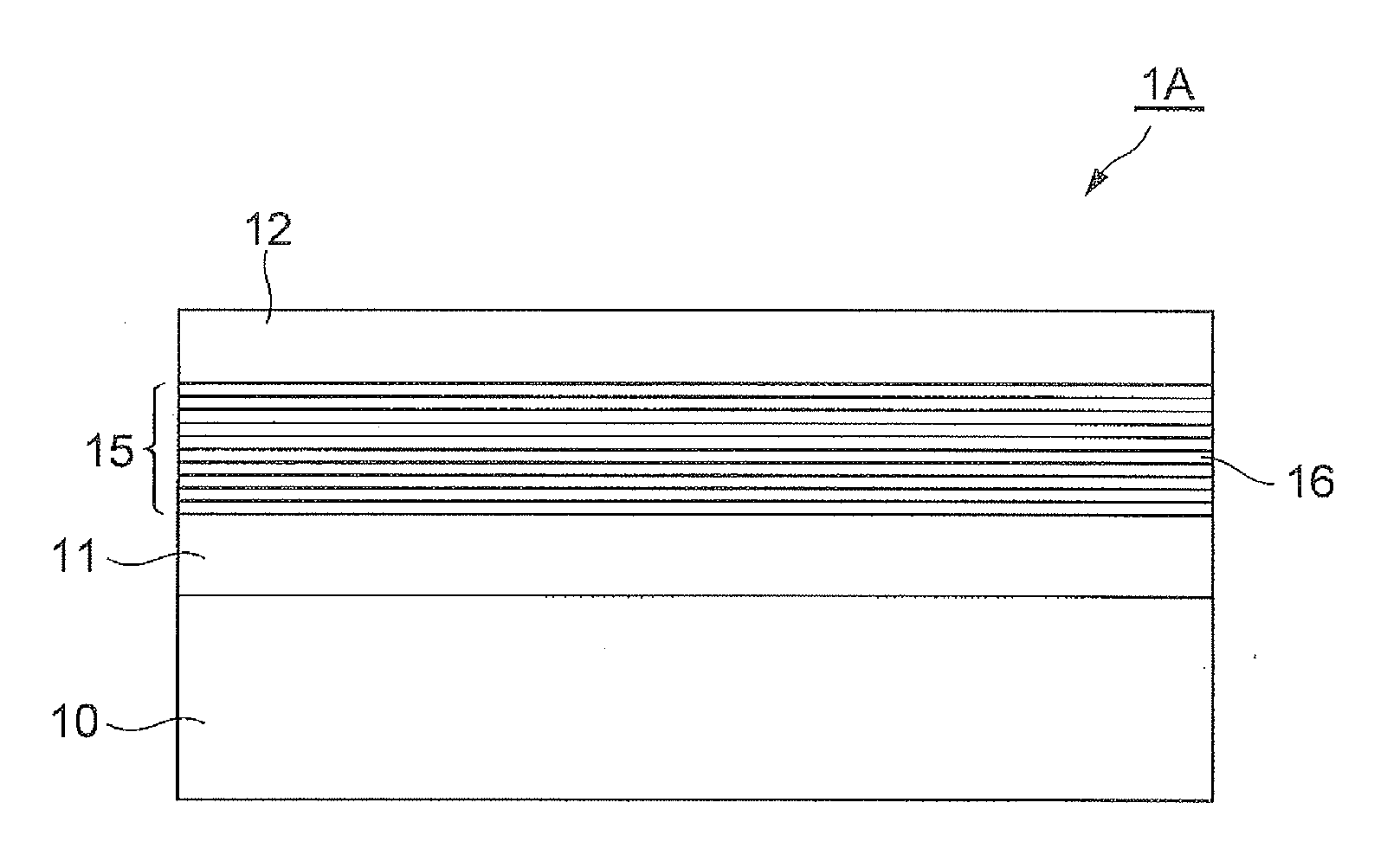
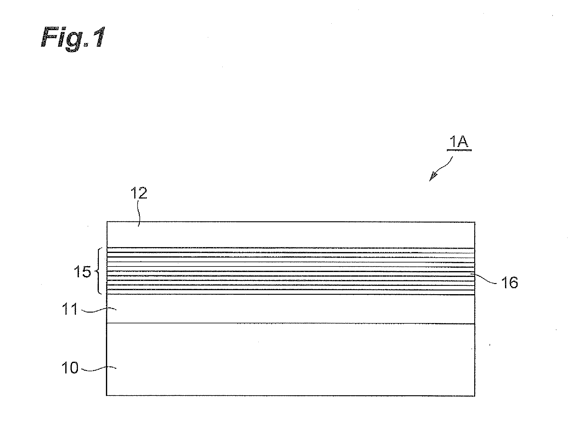
[0028]FIG. 1 is a diagram schematically showing an example of a basic configuration of a quantum cascade detector according to the present invention. A quantum cascade detector 1A according to the present embodiment is a photodetector that detects light by utilizing light absorption using intersubband electron excitation in a semiconductor quantum well structure. This quantum cascade detector 1A includes a semiconductor substrate 10, and an active layer 15 formed on the semiconductor substrate 10.

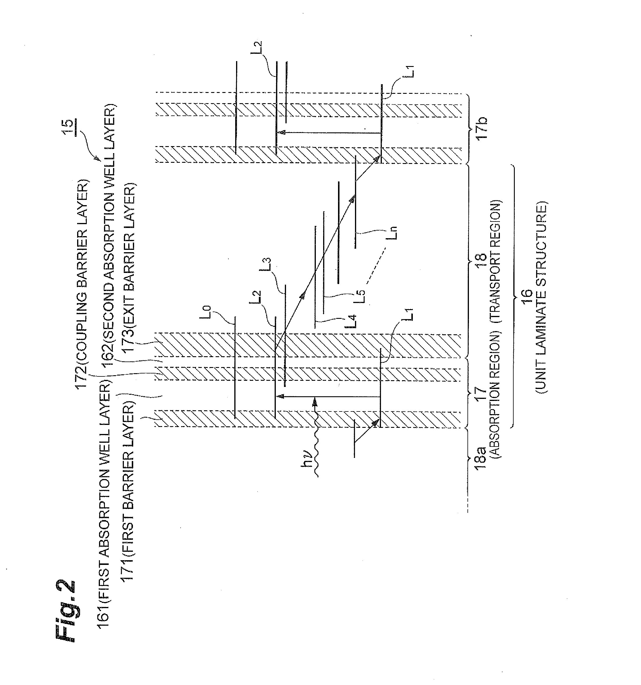
[0029]The active layer 15 has a cascade structure formed by alternately multistage-laminatin...


PUM


Abstract

A quantum cascade detector includes a semiconductor substrate, and an active layer formed by laminating unit laminate structures each having an absorption region with a first barrier layer to a second well layer and a transport region with a third barrier layer to an n-th well layer. A second absorption well layer has a layer thickness ½ or less of that of a first absorption well layer thickest in one period, and a coupling barrier layer has a layer thickness smaller than that of an exit barrier layer thickest in one period. The unit laminate structure has a detection lower level arising from a ground level in the first well layer, a detection upper level generated by coupling an excitation level in the first well layer and a ground level in the second well layer, and a transport level structure for electrons.

Description

BACKGROUND OF THE INVENTION[0001]1. Field of the Invention[0002]The present invention relates to a quantum cascade detector utilizing intersubband light absorption in a quantum well structure.[0003]2. Related Background Art[0004]As a photodetector in the mid-infrared wavelength region, normally, a HgCdTe (MCT) detector is used. However, this MCT detector has a problem such as containing toxic environmental pollution materials, so that the MCT detector cannot be generally and widely used. Therefore, a novel photodetector in such a wavelength region has been demanded.[0005]In recent years, as such a photodetector, quantum cascade detectors (QCD) using GaAs / AlGaAs quantum cascade structures, etc., have been reported. A quantum cascade detector is a photodetector which absorbs light in its cascade structure, and by measuring the amount of current flowed by carriers generated by the light absorption, detects incident light, and is operable with no bias. Further, in the quantum cascade de...

Claims


Application Information

Patent Timeline
Patent Type & Authority Applications(United States)
IPC IPC(8): H01L31/0352
CPCH01L31/035236H01L31/06875H01L31/09H01L31/105
Inventor FUJITA, KAZUUEHIROHATA, TORUEDAMURA, TADATAKADOUGAKIUCHI, TATSUO
Owner HAMAMATSU PHOTONICS KK
Why Eureka
Try Eureka