Passive wireless self-resonant sensor

a self-resonant sensor and wireless technology, applied in the field of sensors, can solve the problems of reducing reducing the surface area of traditional coating techniques, such as spin coating, and utilizing dissolution, so as to improve the coupling between the sensor and the reader, improve the effect of the coupling and simplify the fabrication

Inactive Publication Date: 2015-05-07
BOARD OF RGT THE UNIV OF TEXAS SYST
View PDF15 Cites 17 Cited by
  • Summary
  • Abstract
  • Description
  • Claims
  • Application Information

AI Technical Summary

Benefits of technology

[0005]The present invention provides a passive wireless self-resonant sensor having: (1) high responsiveness to changes in a liquid by conformal coating of a polymer on an open nanowire mat that allows the manipulation of surface properties within capillary-like voids to select what liquid may enter those voids and be sensed; (2) improved coupling between the sensor and reader by putting the capacitor in the interwinding area of the inductor; and (3) simplified fabrication because only one metal layer patterning step is required. The passive wireless self-resonant sensor can monitor both the dielectric constant and conductivity of target specific materials under test (e.g., chemical compounds, pH, hydrocarbons, fluids, gases, etc.), which are detected via changes in the resonance frequency and phase dip. Moreover, the passive wireless self-resonant sensor is disposable and can be used in high temperature environments.

Problems solved by technology

Traditional sensor designs that connect separate inductor and capacitive transducer to form a LC resonant structure has two weaknesses: (1) the capacitor is put in the middle of the spiral inductor, reducing the coupling between sensor and reader; and (2) fabrication requires two photolithography steps.
Moreover, traditional coating techniques, such as spin coating, that utilize dissolution suffer from a lack of surface area resulting from the polymer filling gaps, rather than conforming to the surfaces.
As a result, their responsiveness to changes in liquid may the limited due to slow kinetic changes.

Method used


Image

  • Passive wireless self-resonant sensor
  • Passive wireless self-resonant sensor
  • Passive wireless self-resonant sensor

Examples


Embodiment Construction

[0058]While the making and using of various embodiments of the present invention are discussed in detail below, it should be appreciated that the present invention provides many applicable inventive concepts that can be embodied in a wide variety of specific contexts. The specific embodiments discussed herein are merely illustrative of specific ways to make and use the invention and do not delimit the scope of the invention. The discussion herein relates primarily to chemical sensors and electronics, but it will be understood that the concepts of the present invention are applicable to any self-resonant sensor.

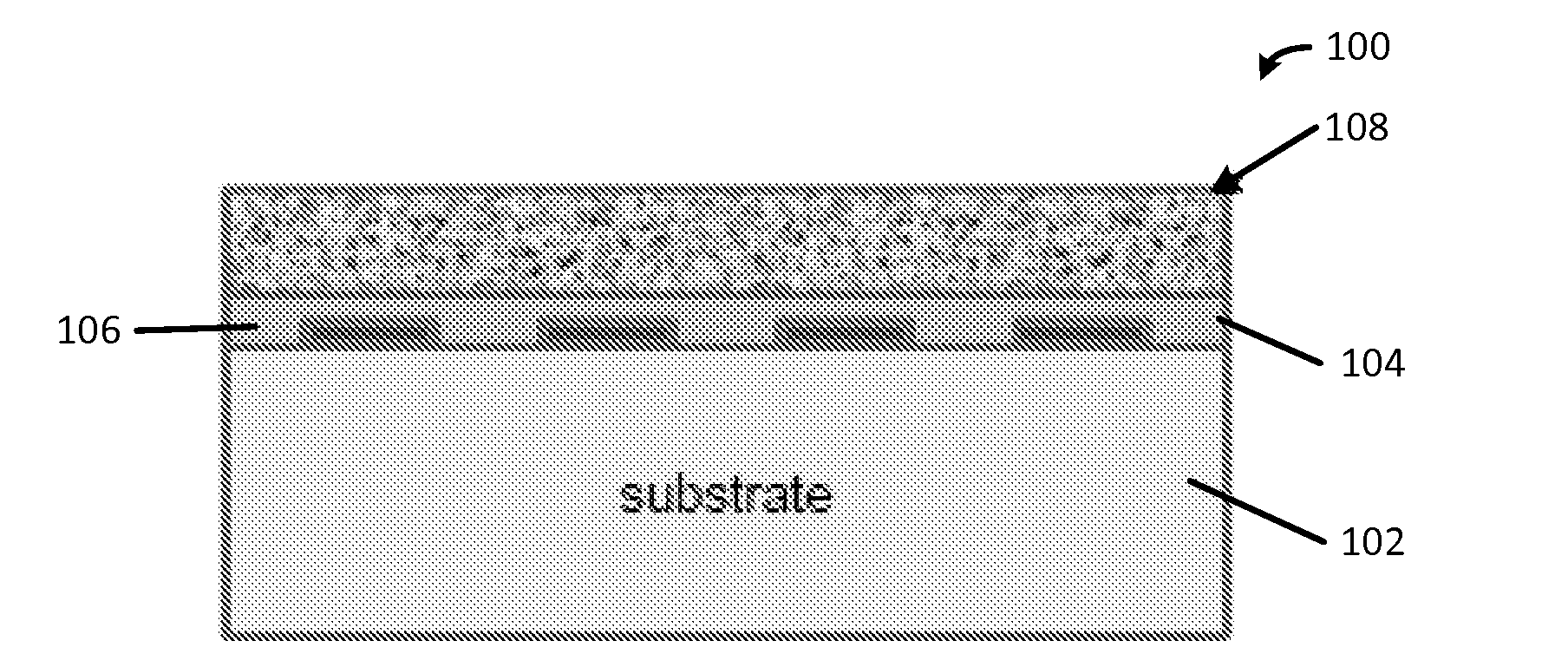
[0059]The present invention provides a wireless self-resonant sensor having: (1) high responsiveness to changes in a liquid by conformal coating of a polymer on a high surface area material, such as an open nanowire mat, that allows the manipulation of surface properties within capillary-like voids to select what liquid may enter those voids and be sensed; (2) improved couplin...


PUM

PropertyMeasurementUnit
lengthaaaaaaaaaa
lengthaaaaaaaaaa
resonant frequencyaaaaaaaaaa

Abstract

A sensor for detecting one or more materials includes a substrate, a passivation layer formed on the substrate, a self-resonant structure and a high surface area material disposed on the passivation layer. The self-resonant structure includes a planar spiral inductor and a plurality of planar interdigitated capacitor electrodes disposed within the passivation layer. The planar spiral inductor includes an electrically conductive trace formed on the substrate in a planar spiral pattern having at least two turns and an inter-winding space between parallel segments of the electrically conductive trace. The plurality of planar interdigitated capacitor electrodes are electrically connected to the electrically conductive trace of the planar spiral inductor and formed on the substrate within the inter-winding space of at least one outermost turn of the planar spiral inductor. The high surface area material includes a conformal polymer coating to increase a sensitivity to the one or more materials.

Description

FIELD OF THE INVENTION[0001]The present invention relates generally to the field of sensors and, more particularly, to a passive wireless self-resonant sensor.BACKGROUND ART[0002]Micromachined LC resonant sensors have design trade offs in size and sensitivity as well as size and coupling. Such sensors have to be carefully laid out to optimize sensitivity and read range. Meanwhile, a sensor's fabrication process needs to be low cost. Traditional sensor designs that connect separate inductor and capacitive transducer to form a LC resonant structure has two weaknesses: (1) the capacitor is put in the middle of the spiral inductor, reducing the coupling between sensor and reader; and (2) fabrication requires two photolithography steps.[0003]Moreover, traditional coating techniques, such as spin coating, that utilize dissolution suffer from a lack of surface area resulting from the polymer filling gaps, rather than conforming to the surfaces. In addition, these traditional macroscopicall...

Claims


Application Information

Patent Timeline
Patent Type & Authority Applications(United States)
IPC IPC(8): G01N27/04
CPCG01N27/04G01N27/08
Inventor NEIKIRK, DEAN P.PASUPATHY, PRAVEEN K.ZHANG, SHENGLEONHARDT, BRADEKERDT, JOHN G.KORGEL, BRIAN A.HOLMBERG, VINCENT C.SHIPMAN, CATHERINE D.BOGART, TIMOTHY D.CHOCKLA, AARON
Owner BOARD OF RGT THE UNIV OF TEXAS SYST
Why Eureka
Try Eureka