Reflective colorless optical transmitter

a colorless optical transmitter and colorless technology, applied in the direction of electromagnetic networks, electromagnetic transmission, transmission, etc., to achieve the effect of increasing the saturation input optical power

Inactive Publication Date: 2015-05-07
ELECTRONICS & TELECOMM RES INST
View PDF2 Cites 8 Cited by
  • Summary
  • Abstract
  • Description
  • Claims
  • Application Information

AI Technical Summary

Benefits of technology

[0006]The present invention provides a reflective colorless optical transmitter having saturation input optical power increased.

Problems solved by technology

However, a light source, such as an expensive distributed feedback laser diode (DFB LD), is necessary which has a different wavelength for each subscriber, and, for wavelength management, a specific light source having a different wavelength for each subscriber is required to be in stock in preparation for failure.

Method used


Image

  • Reflective colorless optical transmitter
  • Reflective colorless optical transmitter
  • Reflective colorless optical transmitter

Examples


Embodiment Construction

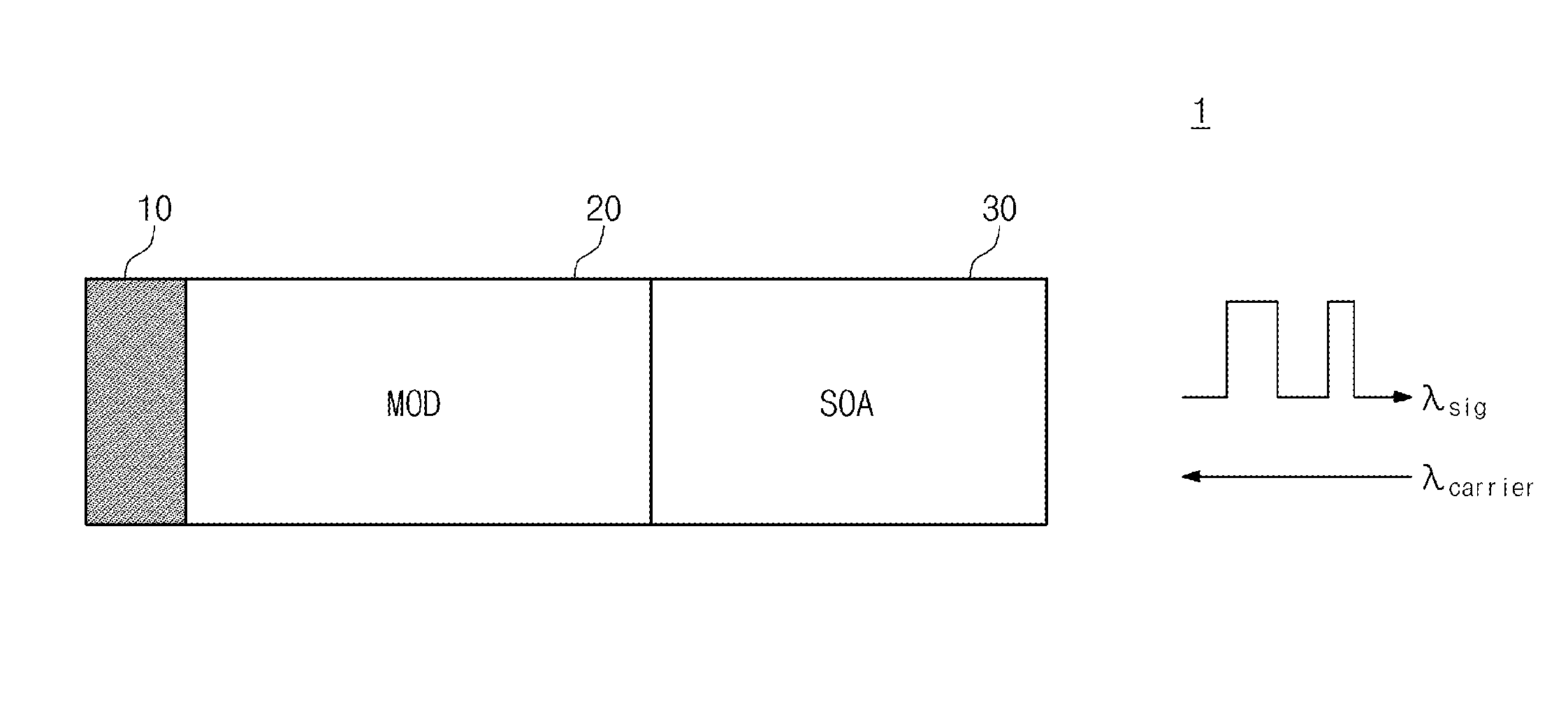
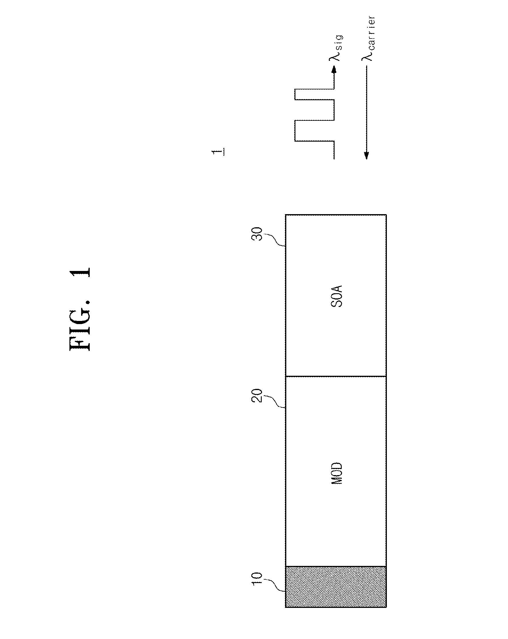
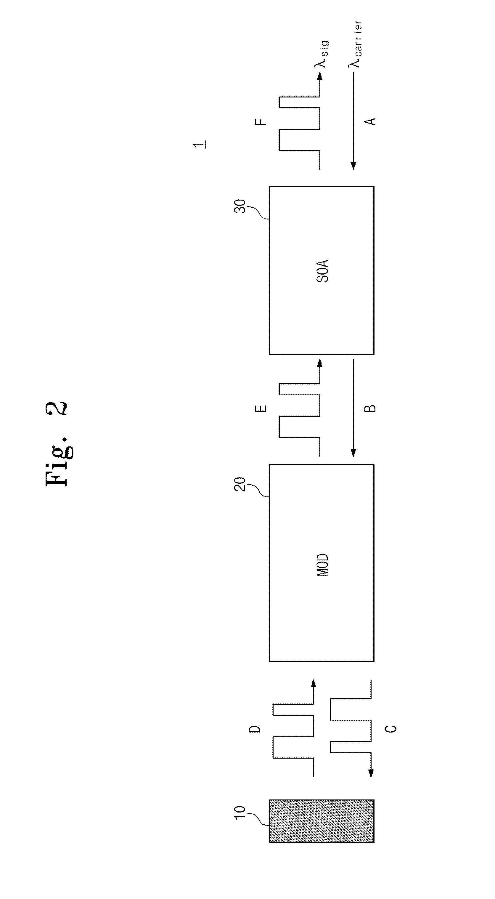
[0034]Preferred embodiments of the present invention will be described below in more detail with reference to the accompanying drawings. The present invention may, however, be embodied in different forms and should not be constructed as limited to the embodiments set forth herein. Rather, these embodiments are provided so that this disclosure will be thorough and complete, and will fully convey the scope of the present invention to those skilled in the art.

[0035]Hereinafter, it will be described about an exemplary embodiment of the present invention in conjunction with the accompanying drawings. In the drawings, parts which are not related to the description are omitted to clearly set forth the present invention and similar elements are denoted by similar reference symbols throughout the specification.

[0036]The terminology used herein is for the purpose of describing particular embodiments only and is not intended to be limiting of example embodiments. As used herein, the singular f...


PUM


Abstract

Provided is a reflective colorless optical transmitter receiving a carrier signal, which is a continuous wave, and outputting a modulated optical signal. The reflective colorless optical transmitter includes a semiconductor optical amplifier (SOA) amplifying an input optical signal allowing the input optical signal to have a gain, an optical modulator connected to the SOA and outputting a modulated optical signal, a high reflectivity facet reflecting the modulated optical signal from the optical modulator, and a Bragg reflection mirror connected to the high reflectivity facet, the optical modulator, and the SOA in series, wherein a Bragg resonator is formed by the Bragg reflecting mirror and the high reflectivity facet.

Description

CROSS-REFERENCE TO RELATED APPLICATIONS[0001]This U.S. non-provisional patent application claims priority under 35 U.S.C. §119 of Korean Patent Application No. 10-2013-0133743, filed on Nov. 5, 2013, the entire contents of which are hereby incorporated by reference.BACKGROUND OF THE INVENTION[0002]The present invention disclosed herein relates to a reflective colorless optical transmitter used for optical communication.[0003]Recently as the ultra high speed internet and various multimedia services are emerged, a fiber to the home (FTTH) technology has been actively developed for connecting a telephone company to a home with an optical fiber to provide mass information transfer. In order to implement the FTTH, various types of optical subscriber networks are required. In implementing the FTTH, the most important conditions are lowering cost as well as mass transfer. The passive optical network (PON) is excellent in network management and maintenance due to characteristics of passive ...

Claims


Application Information

Patent Timeline
Patent Type & Authority Applications(United States)
IPC IPC(8): H04B10/50H04B10/516
CPCH04B10/516H04B10/501H04B10/2587H04B10/272H04B10/50
Inventor KIM, HYUN SOOLEE, DONG-HUNPARK, MI-RANCHOI, BYUNG-SEOKKIM, KISOOKWON, O-KYUN
Owner ELECTRONICS & TELECOMM RES INST
Why Eureka
Try Eureka