

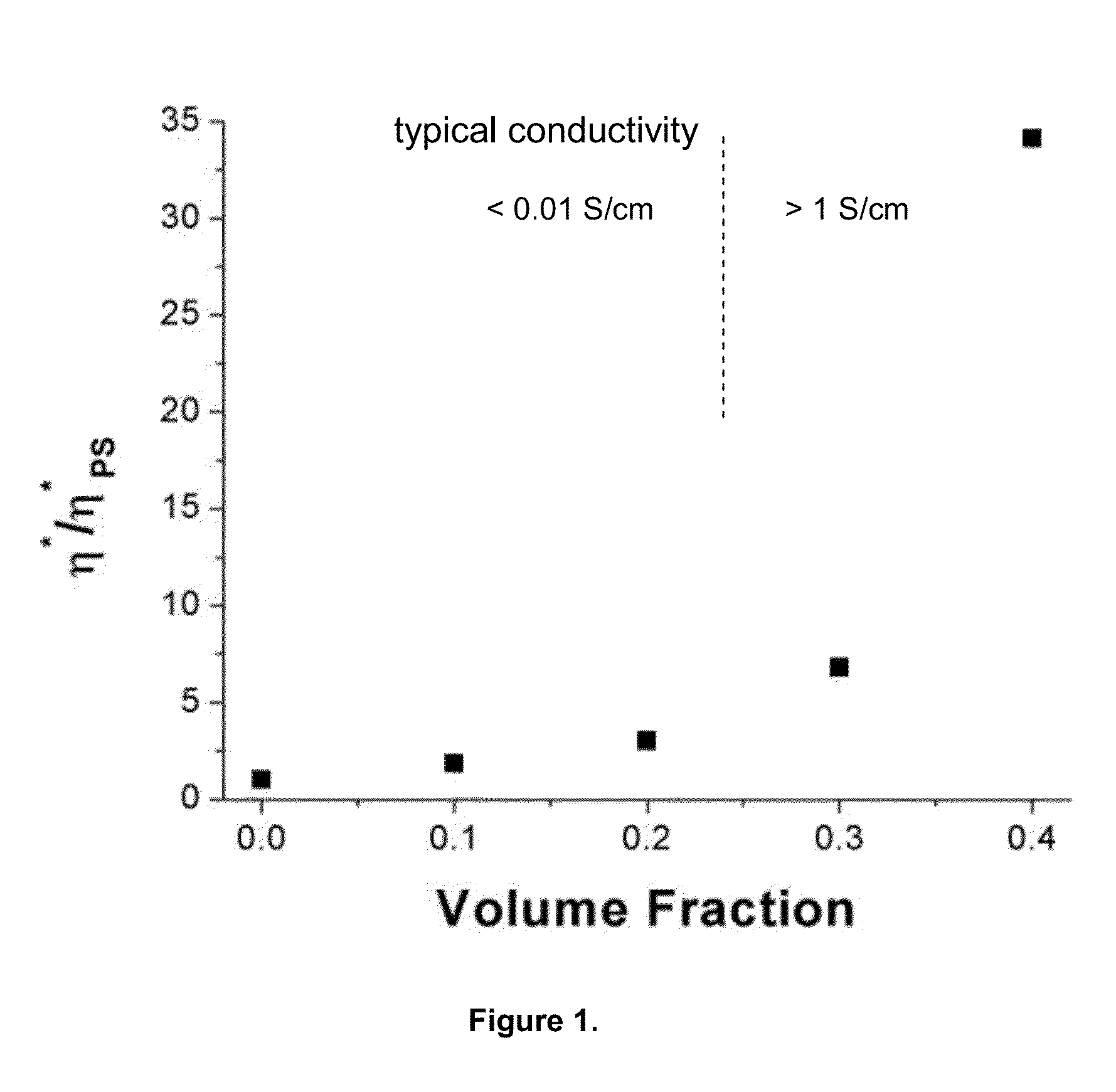
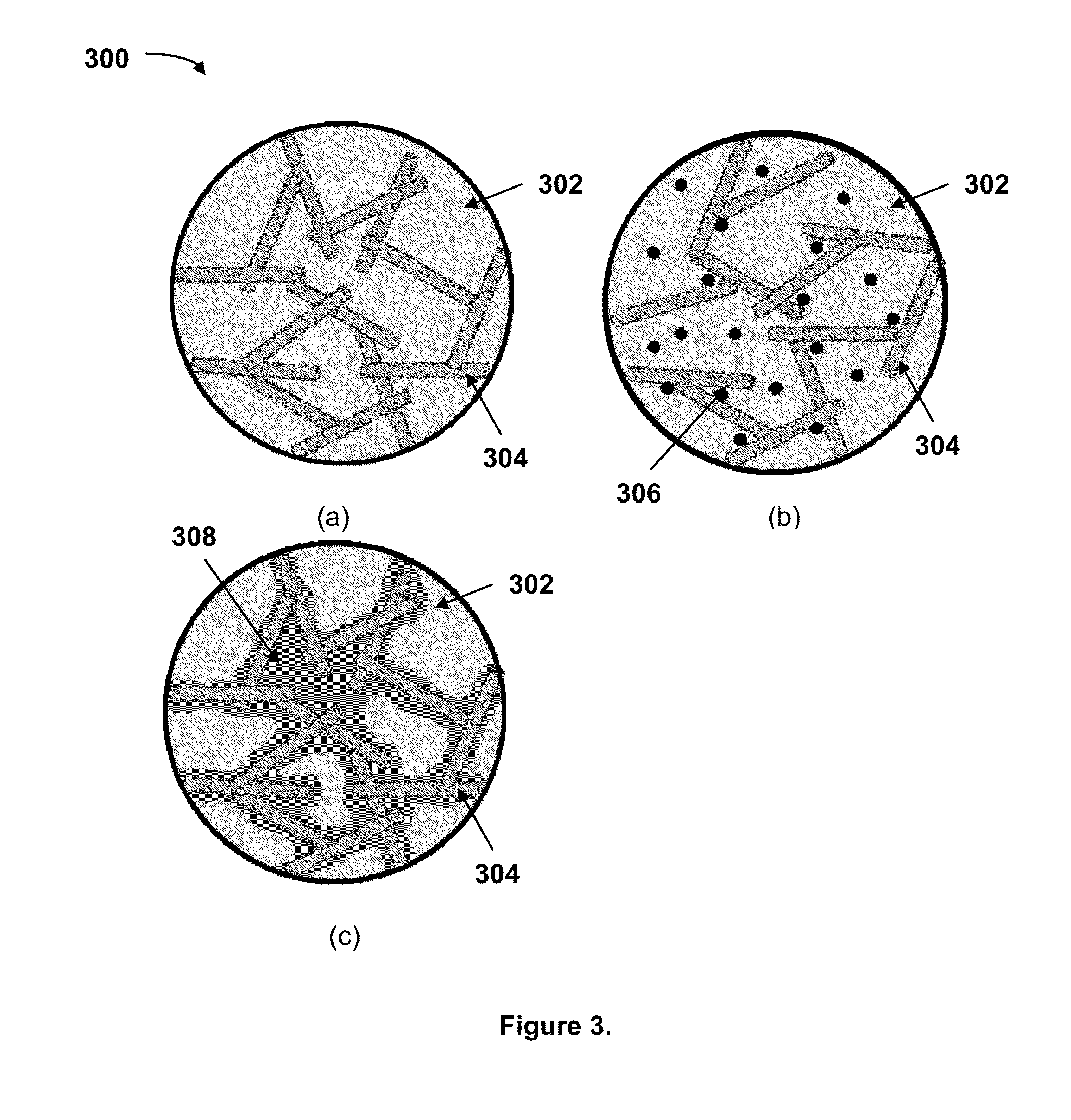
Deformable polymer composites with controlled electrical performance during deformation through tailored strain-dependent conductive filler contact
a technology of conductive filler and deformation resistance, which is applied in the direction of conductors, plastic/resin/waxes insulators, and emergency equipment, etc., can solve the problems of inability to traditional melt processing, material only tolerates modest strain, and is prone to fracture. , the effect of brittle polymer
- Summary
- Abstract
- Description
- Claims
- Application Information
AI Technical Summary
Benefits of technology
Problems solved by technology
Method used
Image

Examples
example 1
Nickel-Coated Carbon Fibers in a Poly(styrene-b-isoprene-b-styrene) Thermoplastic Elastomer Matrix
[0084]Materials
[0085]NCCF was used as-received from Sulzer Metco (Fort Saskatchewan, Alberta, Canada). Poly(styrene-b-isoprene-b-styrene) (SIS) 4111 was used as-received from Dexco Polymers (Houston, Tex., USA).
[0086]Composite Production
[0087]Nickel-coated carbon fiber (NCCF) was mixed with the poly(styrene-b-isoprene-b-styrene) (SIS) 4111 at 25 vol % of NCCF using a DSM conical twin screw extruder (Geleen, Netherlands) at 200° C. and 50 rpm for 15 min. The extrudate was then melt pressed at 160° C. and 20,000 lbf for 3 min to form a ribbon (about 1 cm wide×20 cm long×0.1 cm thick).
[0088]The initial dimensional of the NCCF particles are 10 μm in diameter and 500 μm long on average. The product is listed by the vendor as 67% Nickel by weight. No particle thickness is quoted in the product literature; but SEM images of the particles indicates that the nickel coating on the fibers appears ...
example 2
Liquid Eutectic Metal (Gallium-Indium-Tin) and Nickel-Coated Carbon Fibers in a Poly(styrene-b-isoprene-b-styrene) Thermoplastic Elastomer Matrix
[0100]Materials
[0101]NCCF was used as-received from Sulzer Metco. Poly(styrene-b-isoprene-b-styrene) (SIS) 4111 was used as-received from Dexco Polymers. Galinstan, composed of 68.5% Gallium. 21.5% Indium, and 10% Tin, was used as-received from RG Medical Diagnostics (Wixom, Mich., USA). It has a melting temperature of −2.2° F. (19° C.).
[0102]Composite Production
[0103]The NCCF and Galinstan was mixed with the poly(styrene-b-isoprene-b-styrene) (SIS) 4111 using a DSM conical twin screw extruder (Geleen, Netherlands) at 200° C. and 50 rpm for 15 min. The final composition of the material was 15 vol % NCCF / 25 vol % Galinstan / 60 vol % 4111. The extrudate was then melt pressed at 160° C. and 20,000 lbf for 3 min to press it into a ribbon (approximately 1 cm wide×20 cm long×0.1 cm thick).
[0104]Conductivity as a Function of Elongation
[0105]The con...
example 3
Magnetic Field Orientation of Nickel-Coated Carbon Fibers in a Poly(styrene-b-ethylene-co-butylene-b-styrene) / Mineral Oil Thermoplastic Elastomer Gel Matrix
[0106]Materials
[0107]NCCF were used as-received from Sulzer Metco. Poly(styrene-b-ethylene-co-butylene-b-styrene) (SEBS) G1652 linear block copolymer was used as-received from Kraton Polymers (Houston, Tex., USA). Mineral oil was used as-received from VWR (Suwanee, Ga., USA).
[0108]Composite Production
[0109]SEBS and mineral oil were mixed and heated to 150° C. for 3 h in a ratio of 80% SEBS and 20% mineral oil while stirring occasionally to ensure uniform mixing. The NCCFs were added at 1 vol % and the mixture was mechanically stirred for 15 min at 150° C. Samples were placed between two glass slides with a 1 mm spacer to control the sample thickness. The sample was then placed on a single macrostructured magnet that was patterned with 3 mm spacing or sandwiched between two macrostructured magnets in an oven at 120° C. After 10 mi...
PUM
| Property | Measurement | Unit |
|---|---|---|
| vol % | aaaaa | aaaaa |
| conductivity | aaaaa | aaaaa |
| length | aaaaa | aaaaa |
Abstract
Description
Claims
Application Information