Intervertebral implant

Active Publication Date: 2015-06-04
METAL INDS RES & DEV CENT
View PDF10 Cites 10 Cited by
  • Summary
  • Abstract
  • Description
  • Claims
  • Application Information

AI Technical Summary

Benefits of technology

[0022]The intervertebral implant of the present invention is formed of a plurality of metal balls having a uniform particle diameter, and has a number of areas, each area being filled with a mixture having a different weight percentage of the pore-making agent mixed in the metal powder particles. After vacuum sintering, each area has a different quantity of metal balls, and is formed into a porous structure having a different porosity and pore size. The porous structures enable bone growth in pores, thereby improving degree of fusion of the implant and a bone, and pores of each area are evenly distributed and pore sizes are uniform; therefore, generated stress are also uniform, thereby achieving higher mechanical compatibility.
[0023]In the intervertebral implant of the present invention, because each layer has a different porosity and pore size, the intervertebral implant can also achieve a multiple stiffness effect with

Problems solved by technology

An existing intervertebral fusion implant has problems such as an undesirable fusion effect and dislocation after bone implantation.
However, in the case of utilizing additional adding manners, the manners have problems such as a short release period and uneven concentration in local areas.
However, for the central portion that has bony trabeculae-form irregular pores, such a structure is diffi

Method used


Image

  • Intervertebral implant
  • Intervertebral implant
  • Intervertebral implant

Examples


Embodiment Construction

[0034]To further understand the objectives, structural features, and functions of the present invention, related embodiments will be illustrated in detail below with reference to the accompanying drawings:

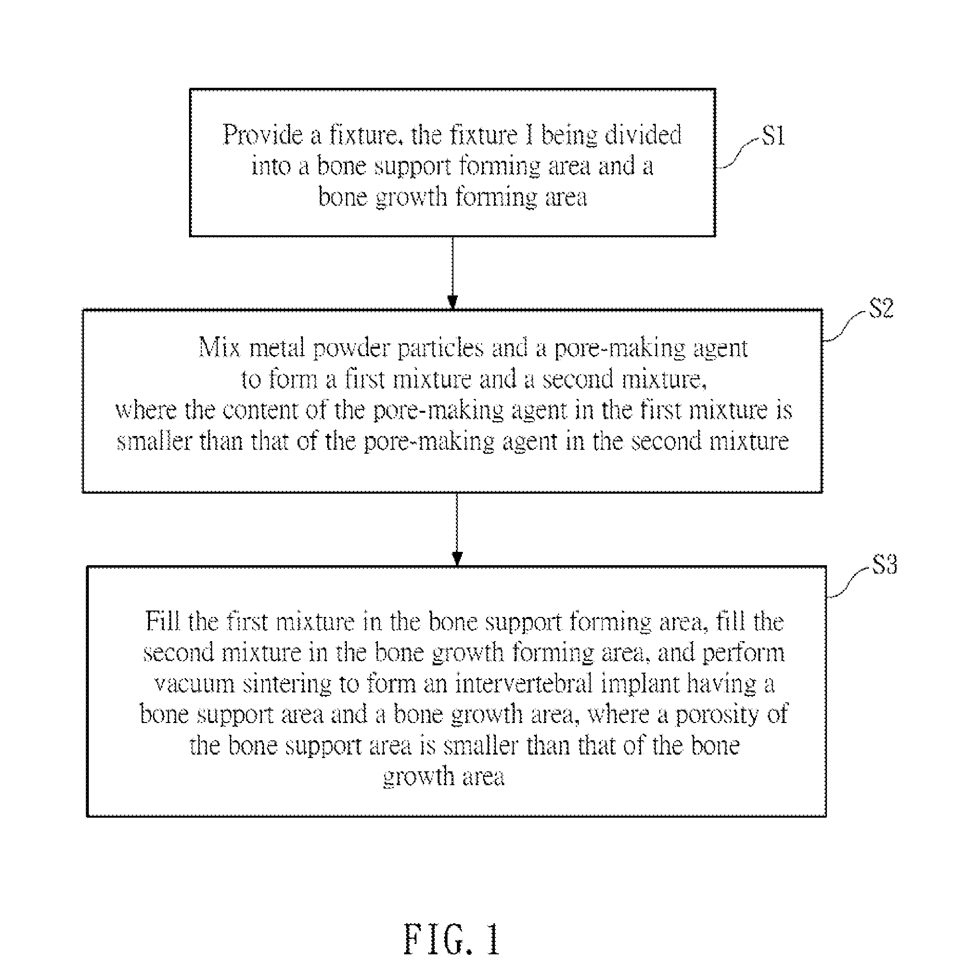
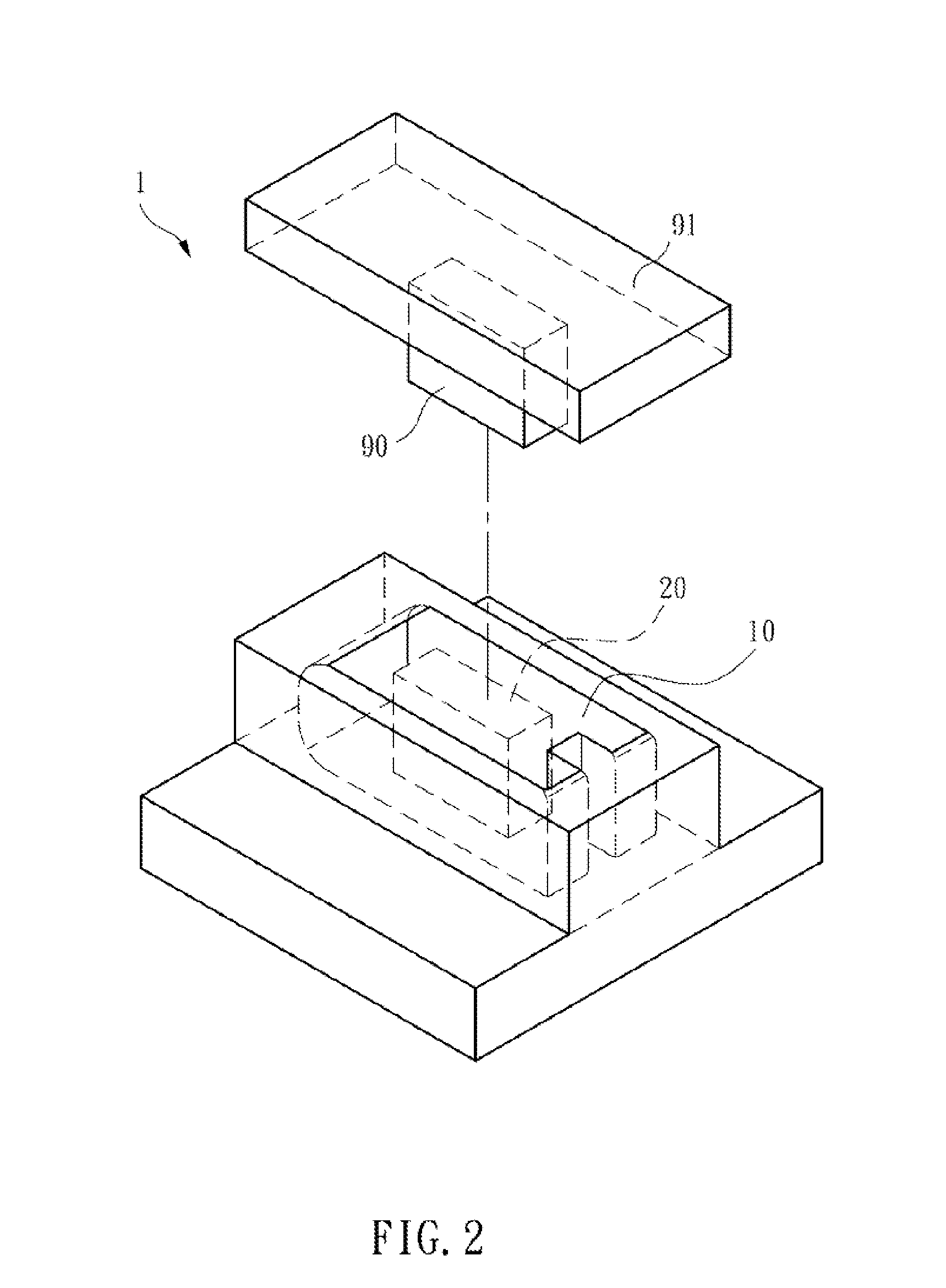
[0035]Please refer to FIG. 1 and FIG. 2. FIG. 1 is a flow chart of a method of fabricating an intervertebral implant according to the present invention. FIG. 2 is a schematic exploded view of a fixture in a method of fabricating an intervertebral implant according to the present invention.

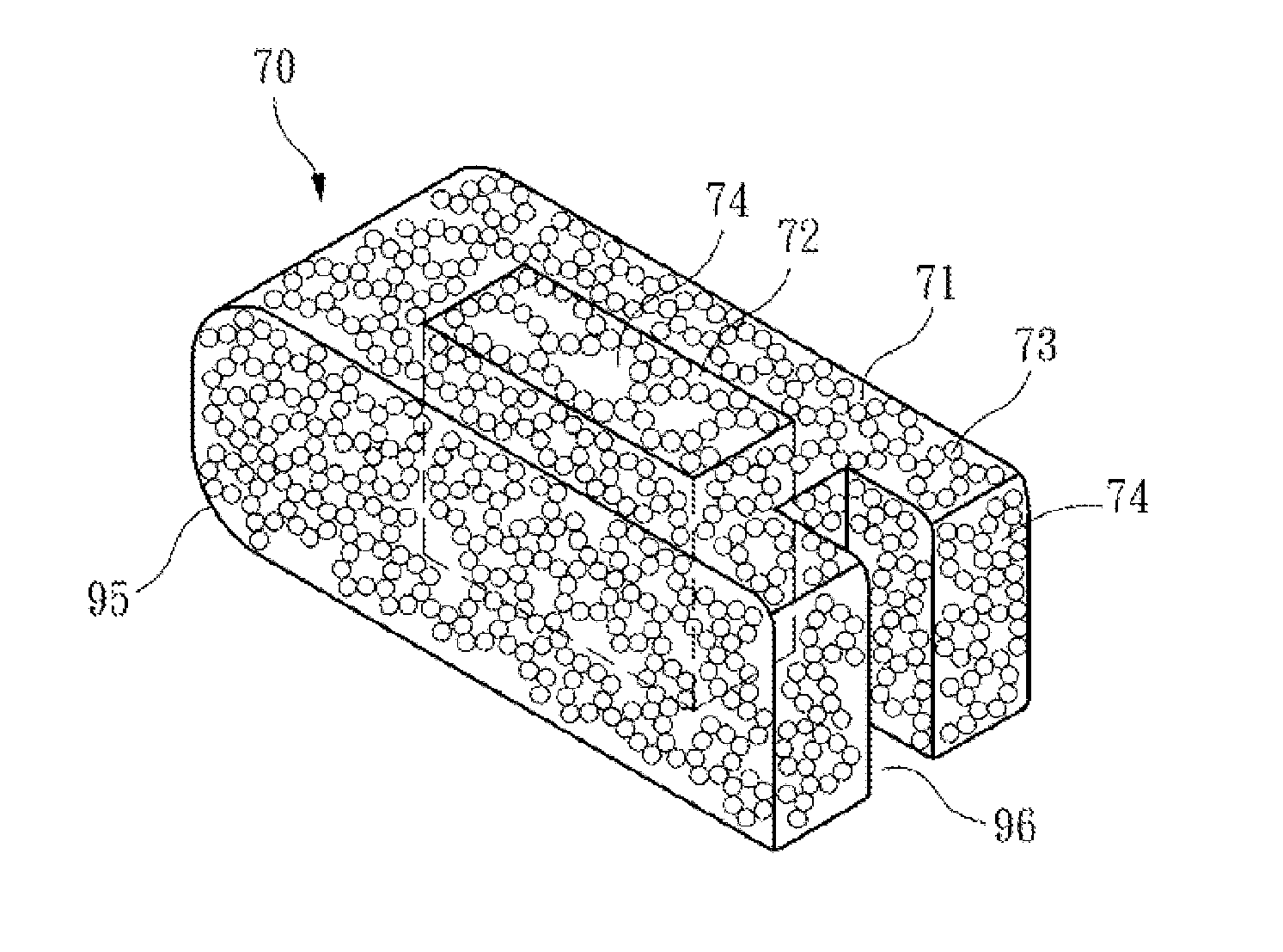
[0036]A method of fabricating an intervertebral implant of the present invention includes the following steps: First, in Step S1, provide a fixture 1, the fixture 1 being divided into a bone support forming area 10 and a bone growth forming area 20, a central block 90, and a top cover 91.

[0037]The fixture 1 is a mould of an intervertebral implant designed according to desired stiffness performance through simulation and drawing by using a computer.

[0038]The bone growth forming area 20 of the fixtu...


PUM

PropertyMeasurementUnit
Sizeaaaaaaaaaa
Sizeaaaaaaaaaa
Porosityaaaaaaaaaa

Abstract

An intervertebral implant is a porous structure formed of a plurality of metal balls, and the intervertebral implant includes a bone support area and a bone growth area. The bone support area and the bone growth area each have a plurality of connecting holes, and a porosity of the bone support area is smaller than that of the bone growth area.

Description

CROSS-REFERENCE TO RELATED APPLICATION[0001]This application claims the benefit of Taiwan Patent Application No. 102143685, filed on Nov. 29, 2013, which is hereby incorporated by reference for all purposes as if fully set forth herein.BACKGROUND OF THE INVENTION[0002]1. Field of Invention[0003]The present invention relates to an intervertebral implant, and more particularly to an intervertebral implant formed of a plurality of metal balls having a uniform particle diameter; the intervertebral implant has a number of areas, where each area is formed with a different porosity and pore size based on a different forming quantity of metal balls, making the intervertebral implant a composite pore structure having multiple stiffness.[0004]2. Related Art[0005]Lumbar interbody fusion is to remove an intervertebral disc from two cervical vertebrae and then to fuse the two cervical vertebrae. Such a step is also referred to as “spinal fusion”, and is usually used for treating patients sufferi...

Claims


Application Information

Patent Timeline
IPC IPC(8): A61F2/44B22F7/08B22F5/00B22F3/10
CPCA61F2/447B22F3/10A61F2310/00011B22F5/00B22F7/08A61F2002/30011A61F2002/30593A61F2002/30957A61F2002/30968A61F2310/00023A61L27/04A61L27/56A61L2430/38B22F3/1109B22F3/1121B22F7/06C22C1/0458
Inventor WANG, WEI-CHINGCHEN, YEN-NIENSUE, TZYY-KERWANG, FOR-SONSHIH, WEI-JENCHEN, WEI-TE
Owner METAL INDS RES & DEV CENT
Why Eureka
Try Eureka