Amplifier circuit with cross wiring of direct-current signals and microwave signals

a technology of direct-current signals and amplifier circuits, which is applied in the field of communication technologies, can solve the problems of limiting the freedom of circuit design, symmetrical circuit structure, and limited wiring space of microwave and millimeter-wave integrated power amplifier chips, so as to improve circuit design freedom, reduce circuit sensitivity of elements in the present invention, and symmetrical circuit structure

Active Publication Date: 2015-06-11
NO 55 INST CHINA ELECTRONIC SCI & TECHNOLOGYGROUP CO LTD
View PDF6 Cites 1 Cited by
  • Summary
  • Abstract
  • Description
  • Claims
  • Application Information

AI Technical Summary

Benefits of technology

The present invention provides a transistor core direct-current feeding circuit and a microwave signal circuit that are symmetrical about a HEMT cell, allowing for optimal performance of the transistor core FET. Furthermore, the invention includes a parallel connected second capacitor that can be directly connected to a capacitor in series, improving circuit design flexibility. Compared with prior art, the present invention has a symmetrical circuit structure, lower circuit sensitivity to elements, and significantly improved layout density and chip space utilization rate.

Problems solved by technology

Due to the limit of the chip size, a microwave and millimeter-wave high-power monolithic integrated power amplifier chip has a very limited wiring space in a tail-level circuit layout.
The disadvantage of the circuit implemented in this manner is that passing through the parallel connected capacitors 141, 142, the matching unit needs combining first to be connected to the capacitor 131, which limits the freedom of the circuit design.
Also, the electromagnetic. field of a region 1 is discontinuous, and the microwave matching circuit is also not completely symmetrical about the transistor core.
For a matching circuit having a large grid width, high power, and a high impedance transformation ratio, the performance of the matching circuit will be significantly limited.

Method used


Image

  • Amplifier circuit with cross wiring of direct-current signals and microwave signals
  • Amplifier circuit with cross wiring of direct-current signals and microwave signals
  • Amplifier circuit with cross wiring of direct-current signals and microwave signals

Examples


embodiment 1

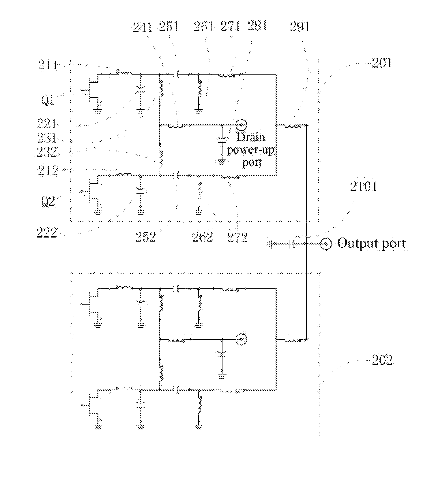
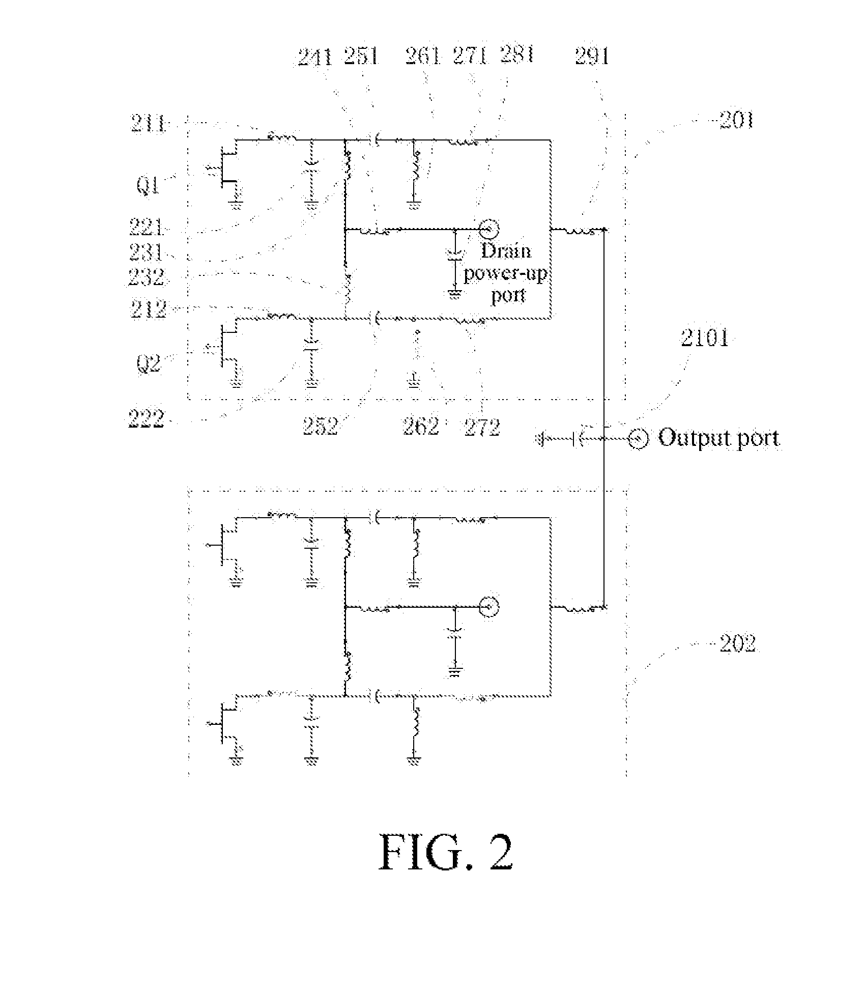
[0018]An amplifier circuit with cross wiring of direct-current signals and microwave signals in this embodiment is fabricated by using a semiconductor monolithic microwave integrated circuit (MMIC) process line, the principle view of the circuit is shown in FIG. 2, and the circuit layout is shown in FIG. 3. During the implementation of the circuit, a serially connected inductor is implemented by using micro-strip lines having different impedance, and a capacitor is implemented by using a lumped Metal-Insulator-Metal (MIM) capacitor. The circuit is formed of two circuit network units 301, 302 that are consistent in amplitude and phase of microwave power signals and are mirror circuits with each other. Each circuit network unit is formed of a direct-current feeding circuit and a microwave signal circuit. The direct-current signal circuit includes a transistor core drain power-up port VdS of a HEMT, a first MIM capacitor 381 connected in parallel, a first micro-strip line 341 connected...


PUM


Abstract

Provided is an amplifier circuit with cross wiring of direct-current signals and microwave signals, which includes: two branch sub-circuits being mirrors with each other and a third capacitor The sub-circuit includes a direct-current feeding circuit and a microwave signal circuit. The direct-current feeding circuit further comprising: a transistor core drain power-up port (Vds) of a heterojunction field effect transistor (FET), a first micro-strip inductor, a first capacitor, a pair of third inductors, a pair of branched second inductors. The microwave signal circuit further comprising: A pair of third inductors, a pair of first capacitors, a pair of second capacitors, a pair of ground inductors, a pair of fourth inductors, a serially connected fifth inductor.

Description

FIELD OF THE INVENTION[0001]The present invention relates to an amplifier circuit with cross wiring of direct-current signals and microwave signals, and more particularly to a microwave and millimeter-wave high-power monolithic integrated power amplifier circuit with cross wiring of direct-current signals and microwave signals, and belongs to the field of communications technologies.DESCRIPTION OF RELATED ART[0002]A microwave and millimeter-wave high-power monolithic integrated power amplifier is a core device in a microwave detection and guidance system and is used for amplifying a low-power signal into a high-power signal, which increases the radiation power of an emitter in the system, thereby increasing a detection distance. With the development of a microwave detection and guidance system, it is required to increase a detection distance and also reduce energy consumption, thereby improving efficiency of the amplifier.[0003]In an aspect, a microwave and millimeter-wave high-powe...

Claims


Application Information

Patent Timeline
IPC IPC(8): H03F1/02H03F3/21H03F3/193
CPCH03F1/0205H03F3/193H03F2200/267H03F2200/171H03F3/21H03F3/195H03F3/211H03F2200/108H01L23/66H01L2223/6655H03F2200/391H01L2924/0002H03F1/0283H03F1/565H01L2223/6683H01L2223/665H01L2924/00H03F3/245
Inventor ZHANG, BINTAO, HONGQI
Owner NO 55 INST CHINA ELECTRONIC SCI & TECHNOLOGYGROUP CO LTD
Why Eureka
Try Eureka