Multilayered structure comprising fine fiber cellulose layer

a fiber cellulose and multi-layered technology, applied in the direction of stationary plate conduit assemblies, pulp material addition processes, paper after-treatment, etc., can solve the problems of reducing the loss of air-conditioning energy attributable, becoming a problem, and the “sick house syndrome”, caused by volatile organic compounds, to achieve high moisture permeability, high moisture permeability, and high moisture retention

Active Publication Date: 2015-06-18
ASAHI KASEI FIBERS CORPORATION
View PDF17 Cites 26 Cited by
  • Summary
  • Abstract
  • Description
  • Claims
  • Application Information

AI Technical Summary

Benefits of technology

[0036]Although the multilayered structure of the present invention can be preferably used in all applications requiring large permeability resistance and high moisture permeability as a result of demonstrating both of these physical properties, it can be particularly preferably used as a partitioning material (total heat exchange element) that partitions two types of air having different temperature, humidity or both in energy recovery ventilators for office air-conditioners or home use and the like. Namely, since this energy recovery ventilation element is more permeable to moist air than conventional energy recovery ventilation sheets due to the thin closed portions that partition air, it is highly effective in retaining moisture. Moreover, since the multilayered structure provided by the present invention also has superior durability, the use of this structure in an energy recovery ventilator makes it possible to provide an energy recovery ventilator that demonstrates extremely high humidity exchange efficiency and total energy recovery effectiveness over a long period of time.

Problems solved by technology

Since 30% to 40% of that amount cannot be ventilated from the outside, reducing the loss of air-conditioning energy attributable to ventilation can be said to be an important issue for conserving energy in office buildings.
In addition, so-called “sick house syndrome”, which is caused by volatile organic compounds dissipated by building materials, household items and the like, is also becoming a problem.
Examples of the causes of these problems include increased airtightness of buildings, increased difficulty in circulating air due to the proliferation of air-conditioners, and ease of accumulation of volatile organic compounds within buildings.
However, when attempts are made to promote building ventilation, it becomes difficult to maintain building heating even if air-conditioning is employed, thereby resulting in excessively high energy consumption.
Consequently, attention is being focused on total heat exchangers that are capable of reducing energy consumption by making it difficult for heat or cold to be released to the outside even if ventilation is employed.
In both these cases, since a hydrophobic polymer is used for the base material, adequate moisture permeability is unable to be obtained, and as a result thereof, sufficient thermal conductivity is unable to be obtained for use as an energy recovery ventilation sheet.
However, due to the inadequate moisture permeability, sufficient performance for use as an energy recovery ventilation sheet is unable to be obtained.
However, the multilayered nonwoven fabric structure described in Patent Document 4 was not suitable for use as an energy recovery ventilation sheet due to high air permeability (permeability resistance of 2000 s / 100 ml or less).

Method used


Image

  • Multilayered structure comprising fine fiber cellulose layer
  • Multilayered structure comprising fine fiber cellulose layer
  • Multilayered structure comprising fine fiber cellulose layer

Examples


example 1

[0142]Cotton linter pulp was immersed in water to a concentration of 10% by weight followed by subjecting to heat treatment for 4 hours in an autoclave at 130° C. and repeatedly rinsing the resulting swollen pulp with water to obtain swollen pulp immersed in water.

[0143]The swollen pulp was dispersed in water to a solid content of 1.5% by weight to obtain an aqueous dispersion (400 L) followed by proceeding with beating treatment for 20 minutes on the 400 L of aqueous dispersion using a disk refiner in the form of the Model SDR14 Labo Refiner (pressurized disk type) manufactured by Aikawa Iron Works Co., Ltd. at a disk clearance of 1 mm, and continuing with beating treatment under conditions such that the clearance was subsequently reduced to nearly zero. When samples were taken over time and evaluated according to the Canadian standard freeness (abbreviated CSF) test for pulp as defined in JIS P 8121 to determine CSF values, CSF values were determined to decrease over time, and whe...

examples 2 to 4

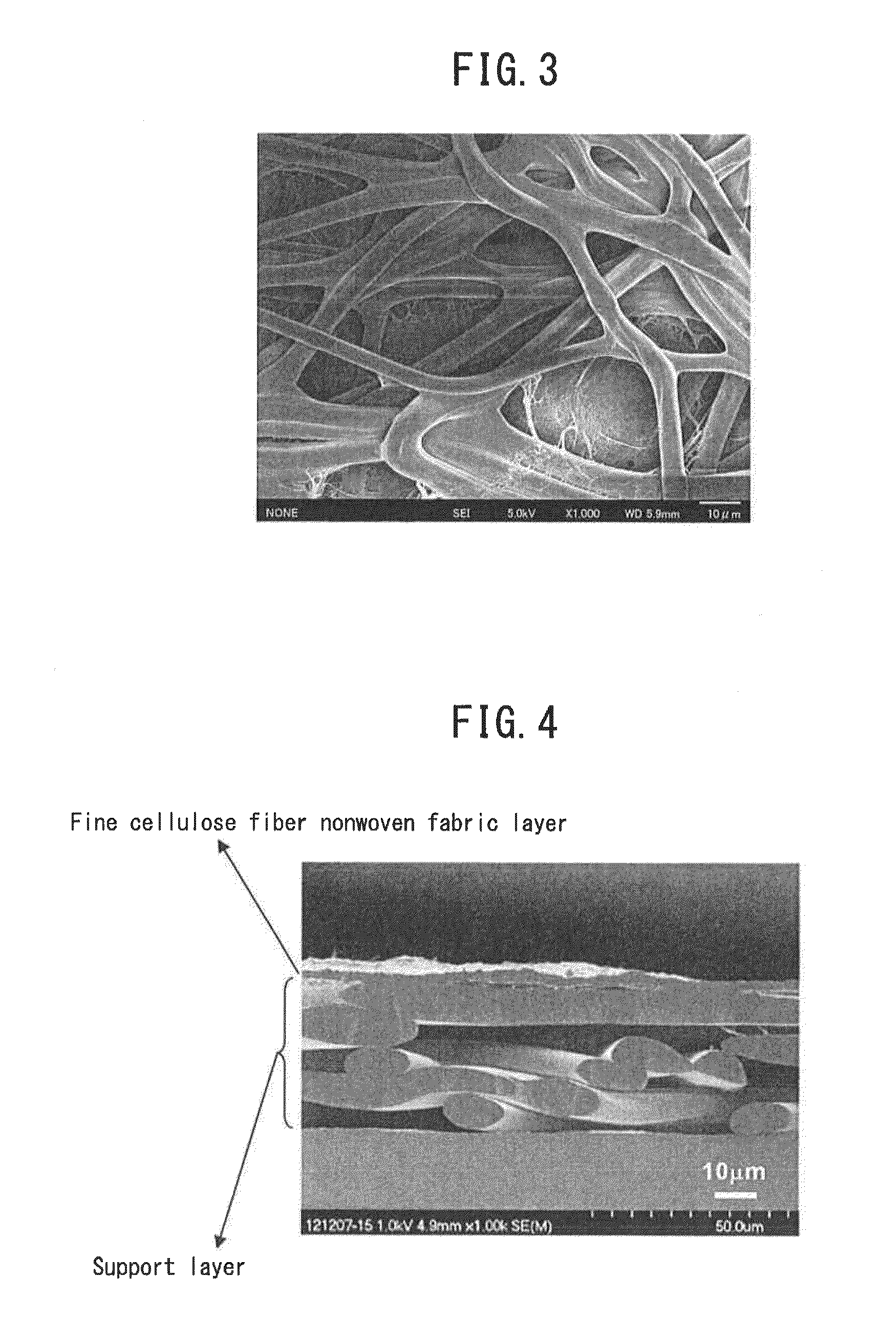
[0146]Papermaking and drying were carried out using the aqueous dispersion slurry M1 of fine cellulose fibers prepared in Example 1 and under exactly the same conditions as Example 1 with the exception of forming a fine cellulose fiber layer equivalent to a basis weight of 5 g / m2 on the cupra rayon nonwoven fabric used in Example 1 to obtain an integrated sheet-like structure S2 (basis weight: 20 g / m2) having double layered structures (Example 2). Although S2 had a lower basis weight of the fine cellulose fiber layer in comparison with S1, it had a tensile strength of 1.1 kg / 15 mm, indicating adequate strength for handling. The thickness of the fine cellulose nonwoven fabric layer of S2 as determined from a cross-sectional SEM image was 3.6 μm.

[0147]Next, calendering treatment (using a roll press manufactured by Yuriroll Co., Ltd.) was carried out on S1 and S2 an in attempt to reduce thickness. A metal roll was used for the upper roll, an aramid roll (hardness: 1.29) was used for th...

examples 5 and 6

[0148]Abaca hemp pulp was immersed in water to a concentration of 10% by weight followed by carrying out heat treatment for 4 hours at 130° C. in an autoclave and repeatedly rinsing the resulting swollen pulp with water to obtain swollen pulp impregnated with water.

[0149]The swollen pulp was dispersed in water to a solid content of 1.5% by weight to obtain an aqueous dispersion (400 L) followed by carrying out beating (beating to a CSF value of 588 ml↑) and downsizing treatment in the same manner as Example 1 to obtain an aqueous dispersion M2 of fine cellulose fibers (solid concentration: 1.5% by weight). Subsequently, dilution with water from M2 and dispersion were carried out using the same procedure as Example 1 to prepare a papermaking dispersion (solid content percentage: 1.5% by weight) followed by carrying out papermaking such that the basis weight of the fine cellulose fiber layer on the cupra rayon base material was 5 g / m2, and carrying out pressing and drying in the same ...


PUM

PropertyMeasurementUnit
densityaaaaaaaaaa
thicknessaaaaaaaaaa
diameteraaaaaaaaaa

Abstract

Provided is a multilayered structure comprising at least one fine cellulose fiber nonwoven fabric layer made of a fine cellulose fiber, wherein the multilayered structure is characterized in that the mean fiber diameter of the fine cellulose fiber forming the fine cellulose fiber non-woven fabric layer is 0.005 to 0.5 μm, and the mean thickness of the multilayered structure is 10 to 200 μm, the density thereof is 0.10 to 0.90 g/cm3, and the permeability resistance thereof is 2000 s/100 ml or more. Also provided are an energy recovery ventilation sheet made of this multilayered structure, an energy recovery ventilation element using this energy recovery ventilation sheet as a partitioning material for partitioning two types of air flow of different temperature and/or humidity, and a energy recovery ventilator using this energy recovery ventilation element.

Description

TECHNICAL FIELD[0001]The present invention relates to a multilayered structure comprising at least one fine cellulose fiber nonwoven fabric layer, an energy recovery ventilation sheet composed of the multilayer structure, an energy recovery ventilation element that uses the energy recovery ventilation sheet as a partitioning material that partitions two types of air flow of different temperature, different humidity or both, and an energy recovery ventilator that uses the energy recovery ventilation element.BACKGROUND ART[0002]Air-conditioning equipment accounts for the largest proportion of energy consumed by ordinary office buildings and other architectural structures (approximately 38%). Since 30% to 40% of that amount cannot be ventilated from the outside, reducing the loss of air-conditioning energy attributable to ventilation can be said to be an important issue for conserving energy in office buildings. In addition, so-called “sick house syndrome”, which is caused by volatile ...

Claims


Application Information

Patent Timeline
Patent Type & Authority Applications(United States)
IPC IPC(8): D21H27/38B32B37/24D21H11/12D21H21/16D21H13/08
CPCD21H27/38D21H21/16D21H13/08B32B2419/00B32B37/24B32B2262/04D21H11/12B32B5/022B32B5/22B32B5/24B32B5/26B32B29/002D21H11/18D21H13/14D21H13/24D21H13/26D21H15/02D21H27/30F24F12/006F28D9/00F28D21/0014F28D21/0015F28F3/00F28F21/00B32B2262/062B32B29/02B32B2255/02B32B2262/0253B32B2262/0261B32B2262/0276B32B2307/3065B32B2307/72B32B2307/7242B32B2307/728Y02B30/56Y02P70/10B32B2307/73D21H21/34
Inventor ONO, HIROFUMITAKASU, SHUJIHORII, ATSUSHIYOSHIDA, SATORU
Owner ASAHI KASEI FIBERS CORPORATION
Why Eureka
Try Eureka