Polyarylene Sulfide Composition for Use in Forming a Laser Direct Structured Substrate

a technology of polyarylene sulfide composition and structured substrate, which is applied in the direction of anti-corrosion paint, synthetic resin layered products, domestic applications, etc., can solve the problems of unsuitable lead free soldering process, difficult laser direct structuring process use, and save space for smaller devices

Inactive Publication Date: 2015-06-25
TICONA LLC
View PDF3 Cites 24 Cited by
  • Summary
  • Abstract
  • Description
  • Claims
  • Application Information

AI Technical Summary

Benefits of technology

[0004]In accordance with one embodiment of the present invention, a polymer composition is disclosed that comprises a polyarylene sulfide matrix within which is dispersed a

Problems solved by technology

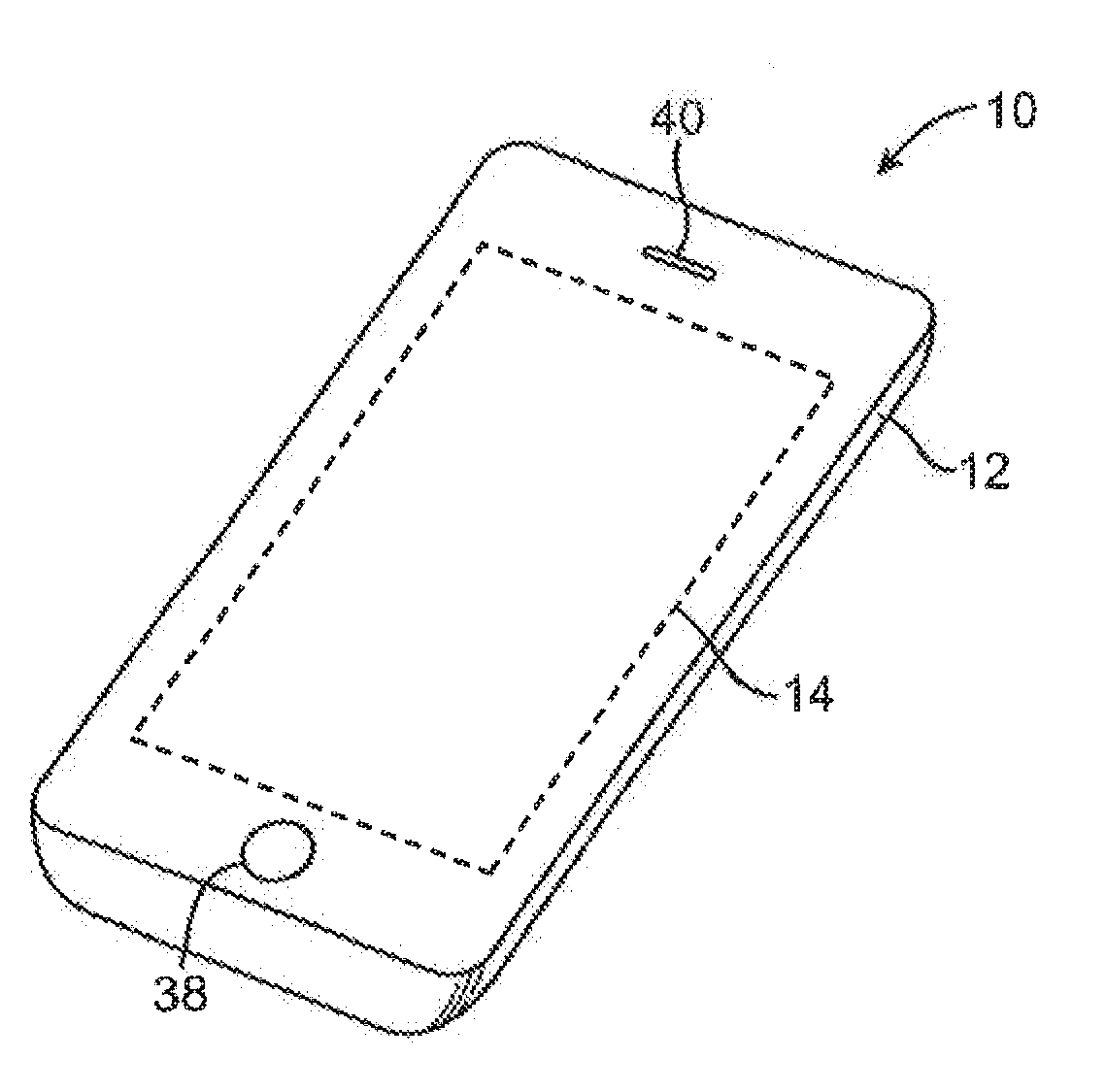
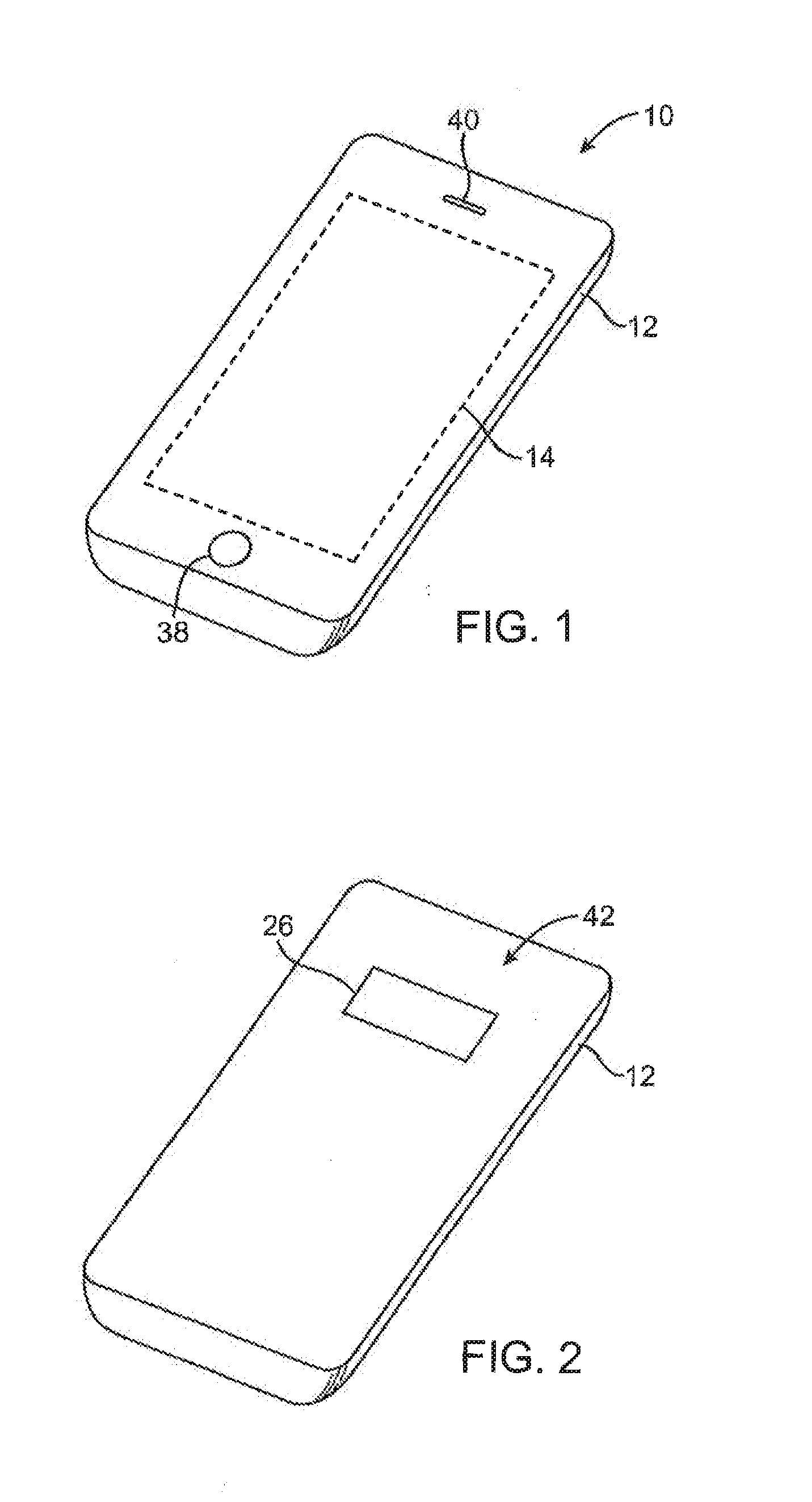
Such MID devices are thus three-dimensional molded parts having an integrated printed conductor or circuit layout, which saves space for use in smaller devices (e.g., cellular phones).
One problem with such materials, however, is that they are unsuitable for lead free soldering proce

Method used


Image

  • Polyarylene Sulfide Composition for Use in Forming a Laser Direct Structured Substrate
  • Polyarylene Sulfide Composition for Use in Forming a Laser Direct Structured Substrate
  • Polyarylene Sulfide Composition for Use in Forming a Laser Direct Structured Substrate

Examples


example 1

[0067]A concentrate is initially formed that contains 70 wt. % of a liquid crystalline polymer and 30 wt. % of a copper chromite filler (CuCr2O4) available from Shepherd Color Co. under the designation Shepherd 1G. The liquid crystalline polymer is formed from 4-hydroxybenzoic acid (“HBA”), 2,6-hydroxynaphthoic acid (“HNA”), terephthalic acid (“TA”), 4,4′-biphenol (“BP”), and acetaminophen (“APAP”), such as described in U.S. Pat. No. 5,508,374 to Lee et al. The polymer is pre-dried for a minimum of 4 hours at 140° C. A twin-screw extruder (Type Berstorff ZE25, 120 mm×25 mm with a main-feed, side-feed and degassing option) is used to compound the two components. The raw materials are initially introduced to the main feed of the extruder as pre-blends (obtained from a powder blender). Vacuum is applied through the vacuum-port of the extruder throughout the entire compounding operation. Once formed, the extruded strands are cooled in a water bath and then pelletized.

example 2

[0068]A concentrate is formed in the same manner described in Example 1, except that it contains 50 wt. % of the liquid crystalline polymer, 30 wt. % of a copper chromite black filler available from Shepherd Color Co. under the designation Dynamix® 30C965, and 20 wt. % mica (Arginotec® SE, dehydrated).

example

[0069]A polymer composition is formed from the concentrate of Example 1 such that the final composition contains 30 wt. % of the concentrate, 29.6 wt. % polyphenylene sulfide (Fortron® 0205B4 SF3001 Natural), 20 wt. % glass fibers (OCV 910, Owens Corning), 20 wt. % talc (HTP 4, IMI FABI) and 0.4 wt. % of triethoxy-aminopropylsilane. The same twin-screw extruder is used as in Example 1. The temperature of the feeding zone is 280° C., and the temperature of Zones 1-12 is 300° C., 300° C., 300° C., 300° C., 300° C., 290° C., 285° C., 310° C., 310° C., 310° C., 310° C., and 340° C., respectively. The screw speed is 200 to 250 rpm and the throughput is 25 kg / hr. The concentrate, PPS, talc, and silane are fed to the main feed, and the glass fibers are fed to a side feed.


PUM

PropertyMeasurementUnit
Compositionaaaaaaaaaa
Weight ratioaaaaaaaaaa
Electrical conductoraaaaaaaaaa

Abstract

A polymer composition formed from a polyarylene sulfide matrix that constitutes a majority of the polymer content of the composition is provided. Although polyarylene sulfides are not typically capable of laser activation, particularly at such a high content of the polymer composition, the present inventor has nevertheless discovered that the resulting composition can still be readily activated with one or more conductive elements using a laser direct structuring process. This is accomplished, in part, by dispersing a combination of a condensation polymer and laser activatable additive within the polyarylene sulfide matrix.

Description

RELATED APPLICATIONS[0001]The present application claims priority to U.S. Provisional Application Ser. No. 61 / 918,098, filed on Dec. 19, 2013, which is incorporated herein in its entirety by reference thereto.BACKGROUND OF THE INVENTION[0002]It is becoming increasingly more common to form metallized electronic components with a laser direct structuring (“LDS”) process during which a computer-controlled laser beam travels over a plastic substrate to activate its surface at locations where the conductive path is to be situated. For example, molded interconnect devices (“MID”) often contain a plastic substrate on which is formed conductive elements or pathways. Such MID devices are thus three-dimensional molded parts having an integrated printed conductor or circuit layout, which saves space for use in smaller devices (e.g., cellular phones). Besides saving space, another advantage of laser direct structuring is its flexibility. If the design of the circuit is changed, it is simply a m...

Claims


Application Information

Patent Timeline
IPC IPC(8): C08L81/04H05K1/03H05K3/18
CPCC08L81/04H05K3/182H05K1/0373C08L2310/00C08L2203/20H05K2203/107H05K2203/11C08L2205/12B32B27/08B32B27/18B32B27/20B32B27/281B32B27/286B32B27/34B32B27/36B32B2262/101B32B2270/00B32B2307/704B32B2457/00C08K3/22C08K3/24C08L67/02C08L67/03C08L81/00H01Q1/243H01Q1/38Y10T428/31533
Inventor SCHAEFER, MICHAEL
Owner TICONA LLC
Why Eureka
Try Eureka