
Material structure prediction apparatus, product manufacturing method and material structure prediction method

a technology of material structure and prediction method, which is applied in the direction of heat treatment process control, process and machine control, computation using non-denominational number representation, etc., can solve the problems of limited application of the method disclosed in the method to a polycrystal metal, change the quality of the material, and the process of repeating test production

Active Publication Date: 2015-06-25
TOSHIBA MITSUBISHI-ELECTRIC IND SYST CORP
View PDF1 Cites 17 Cited by
  • Summary
  • Abstract
  • Description
  • Claims
  • Application Information

AI Technical Summary

Benefits of technology

The invention is a device that can predict the structure of a material that changes its shape when exposed to different temperatures. This patent also describes a method for manufacturing products using this technology. The invention can help in developing new materials that have specific mechanical properties at different temperatures.

Problems solved by technology

However, the process of repeating test production involves much cost and labor.
These factors may well change the quality of the material.
Further, although patent document 2 considers nucleation caused by distortion energy due to dislocation in a single crystal, the application of the method disclosed therein to a polycrystal metal has limitations, because, for example, it is known that in a polycrystal metal such as steel, nucleation may easily occur in the vicinity of the grain boundary of a mother phase structure.
The conventional multi-phase-field method is insufficient in quantitative prediction accuracy since it does not sufficiently consider nucleation behaviors, although it can obtain a qualitative tendency of variation due to grain growth for difference in crystal grain size and shape and these variations in a material structure.
Consequently, it is difficult to apply the disclosed analysis method to a case where quantitative evaluation, such as prediction of material quality after cooling, is needed.
As described above, by the conventional multi-phase-field method, it is difficult for use in the quantitative evaluation of, for example, material quality to predict the structure of a material that exhibits phase transformation as a result of temperature variation.

Method used


Image

  • Material structure prediction apparatus, product manufacturing method and material structure prediction method
  • Material structure prediction apparatus, product manufacturing method and material structure prediction method
  • Material structure prediction apparatus, product manufacturing method and material structure prediction method

Examples


embodiment

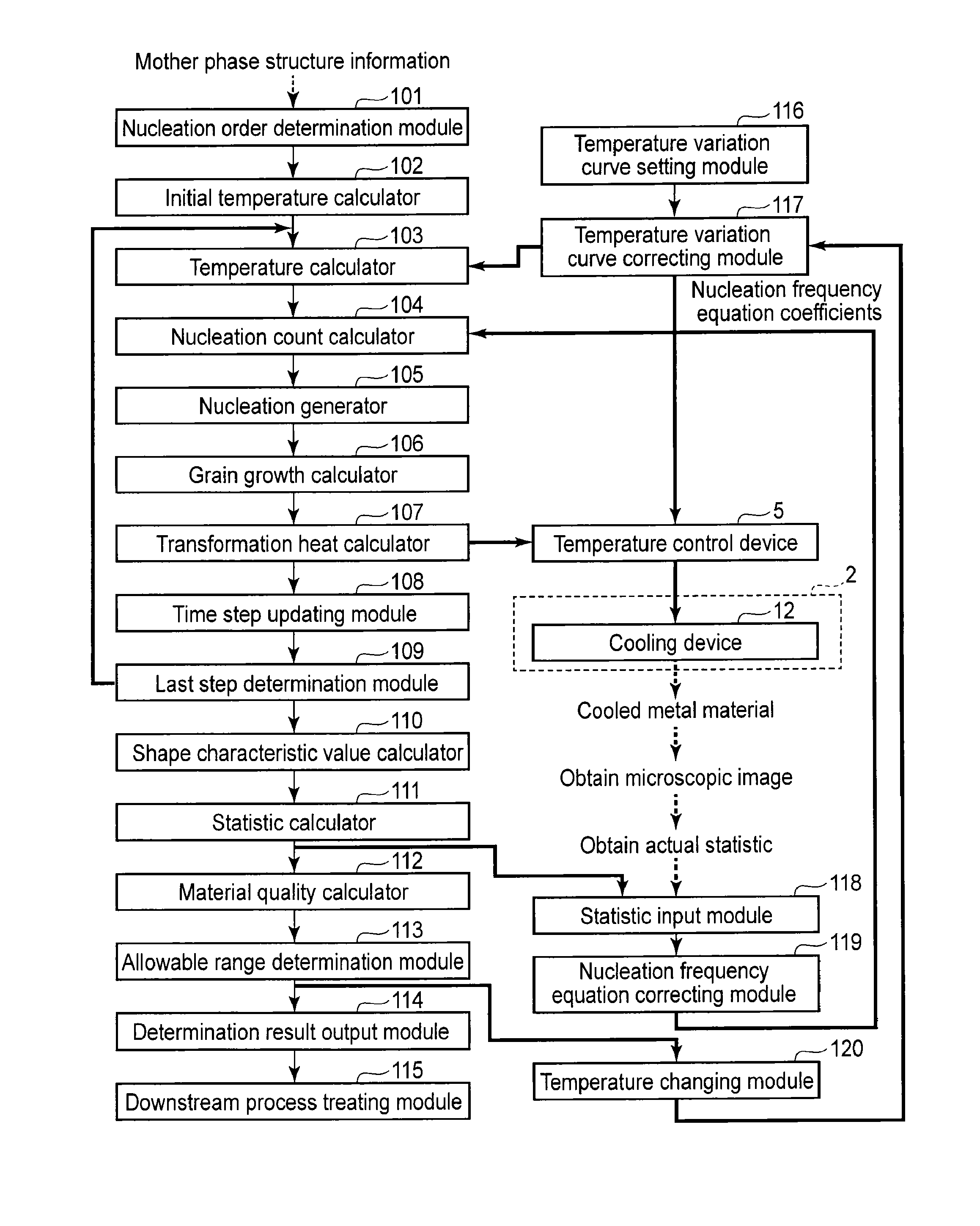
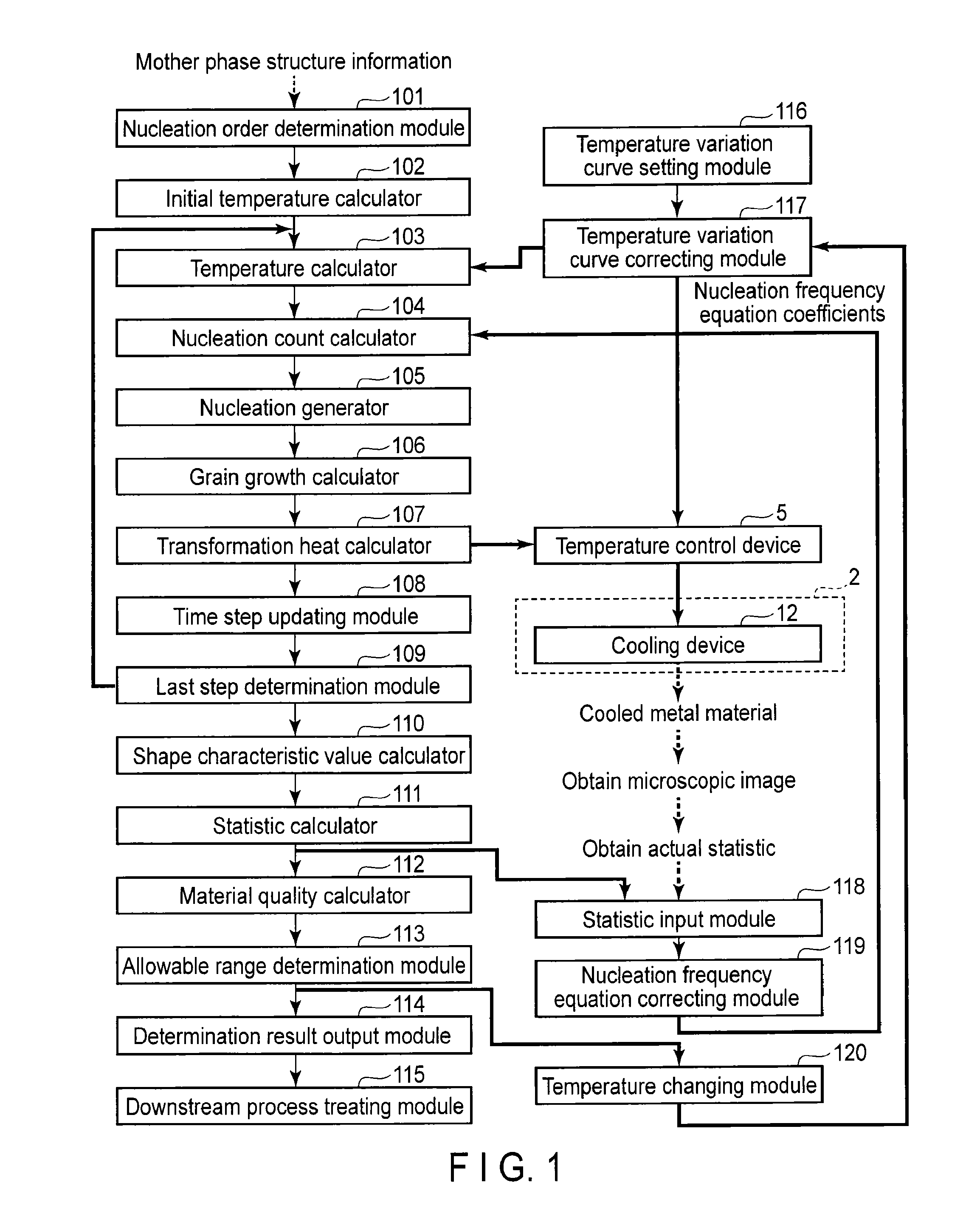
[0027]FIG. 1 is a block diagram showing the configuration of a material structure prediction apparatus 1 according to an embodiment of the invention. In the drawings, like reference numbers denote like portions, the detailed explanations thereof will be omitted, and different portions will be mainly described.

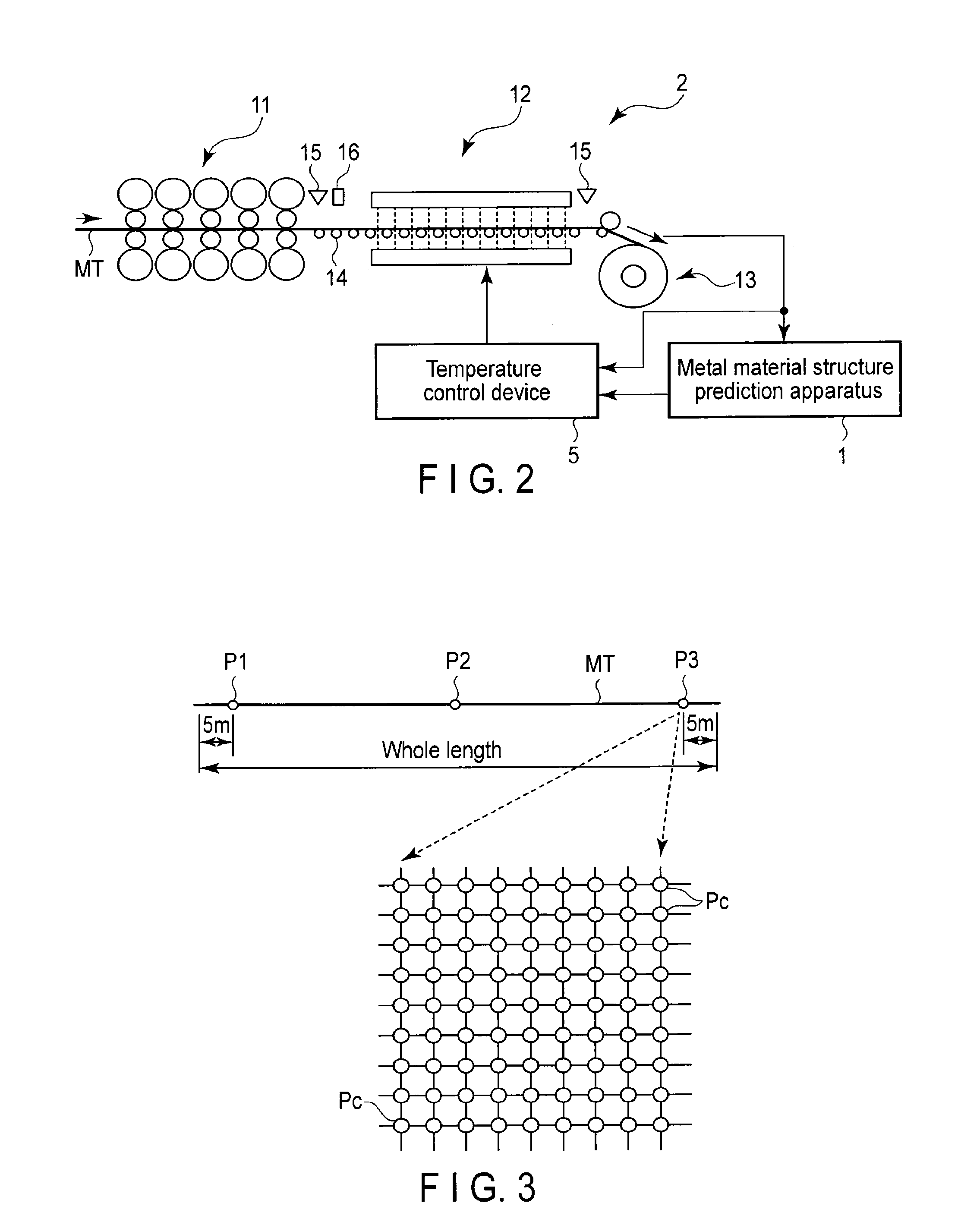
[0028]Firstly, a description will be given of a general metal material processing line to which the material structure prediction apparatus 1 is applied.

[0029]In the metal material processing line, at least heating or cooling is performed on a metal material.

[0030]An induction heating device, a gas heating device, or the like, is used as a heating device. A water cooling device, an oil cooling device, a forced air cooling device, or the like, may be used as a cooling device. A plurality of heating devices and / or cooling devices may be employed. Further, the order of arrangement of the heating and cooling devices can be set arbitrarily.

[0031]A description will be given of a stru...


PUM

PropertyMeasurementUnit
Temperatureaaaaaaaaaa
Structureaaaaaaaaaa
Diffusion coefficientaaaaaaaaaa

Abstract

The material structure prediction apparatus includes a temperature calculator calculating temperatures at calculation points, based on a temperature condition, a nucleation count calculator calculating a nucleation count in the calculation target region, a precipitated phase generation point determining module determining, from the calculation points, a precipitated phase generation point, a grain growth calculator calculating a grain growth of the precipitated phase at the precipitated phase generation point, and a material structure prediction module predicting the structure of the material, based on the grain growth of the precipitated phase.

Description

CROSS REFERENCE TO RELATED APPLICATIONS[0001]This application is a Continuation Application of PCT Application No. PCT / JP2012 / 072234, filed Aug. 31, 2012, the entire contents of which are incorporated herein by reference.BACKGROUND OF THE INVENTION[0002]1. Field of the Invention[0003]The present invention relates generally to a material structure prediction apparatus capable of predicting the structure of a material that exhibits phase transformation due to variation in temperature, a product manufacturing method and a material structure prediction method.[0004]2. Description of the Related Art[0005]In recent years, there has been a demand to improve the quality of materials used for industrial products in view of environmental protection and energy saving. Further, it is known that such material features as tensile strength, yield stress, expansion, etc., are closely associated with material structure at the microscopic level. In view of this, the material feature of a product has ...

Claims


Application Information

Patent Timeline
IPC IPC(8): G06F17/50G05D23/19G05B15/02C21D11/00G06F17/18
CPCG06F17/50C21D11/00G05D23/1917G05B15/02G06F17/18B21B37/00G01N25/02G01N33/20C21D9/573C21D11/005C21D2211/004G06F2113/24G06F30/20G01N33/204G06F30/00
Inventor SANO, MITSUHIKOOHARA, KAZUHIRO
Owner TOSHIBA MITSUBISHI-ELECTRIC IND SYST CORP
Learn More