Atomic layer deposition of tungsten materials

a technology of atomic layer and tungsten, which is applied in the direction of chemical vapor deposition coating, solid-state devices, coatings, etc., can solve the problems of compromising the structural and operational integrity of the underlying portion of the integrated circuit being formed, the need for more complexity in the chamber design and gas flow technique, and the deposition of tungsten by conventional cvd methods, etc., to achieve the effect of improving conductivity, surface uniformity and production level throughpu

Active Publication Date: 2011-06-21
APPLIED MATERIALS INC
View PDF650 Cites 134 Cited by
  • Summary
  • Abstract
  • Description
  • Claims
  • Application Information

AI Technical Summary

Benefits of technology

[0011]Embodiments of the invention provide an improved process for depositing tungsten-containing materials. The process utilizes soak processes and vapor deposition processes, such as atomic layer deposition (ALD) to provide tungsten-containing materials having significantly improved conductivity, surface uniformity, and production level throughput. In one embodiment, a method for forming a tungsten-containing material on a substrate is provided which includes positioning a substrate within a process chamber, wherein the substrate contains an underlayer disposed thereon, exposing the substrate sequentially to a tungsten precursor and a reducing gas to deposit a tungsten nucleation layer on the underlayer during an atomic layer deposition process, wherein the reducing gas contains a hydrogen / hydride flow rate ratio of about 40:1 or greater, and depositing a tungsten bulk layer on the tungsten nucleation layer. The reducing gas contains a hydride compound, such as silane, disilane, diborane, phosphine, derivatives thereof, or combinations thereof.

Problems solved by technology

These requirements become more critical as substrate size increases, creating a need for more complexity in chamber design and gas flow technique to maintain adequate uniformity.
Formation of film layers at a high deposition rate while providing adequate step coverage are conflicting characteristics often necessitating the sacrifice of one to obtain the other.
Depositing tungsten by conventional CVD methods, however, is attendant with several disadvantages.
Also, blanket deposition of a tungsten layer on a semiconductor wafer is time-consuming at temperatures below 400° C. The deposition rate of tungsten may be improved by increasing the deposition temperature to, for example, about 500° C. to about 550° C. However, temperatures in this higher range may compromise the structural and operational integrity of the underlying portions of the integrated circuit being formed.
Use of tungsten has also frustrated photolithography steps during the manufacturing process as it results in a relatively rough surface having a reflectivity of 70% or less than that of silicon (thickness and wavelength dependent).
Further, tungsten has proven difficult to deposit uniformly.
Poor surface uniformity typically increases film resistivity.

Method used


Image

  • Atomic layer deposition of tungsten materials
  • Atomic layer deposition of tungsten materials
  • Atomic layer deposition of tungsten materials

Examples


example 1

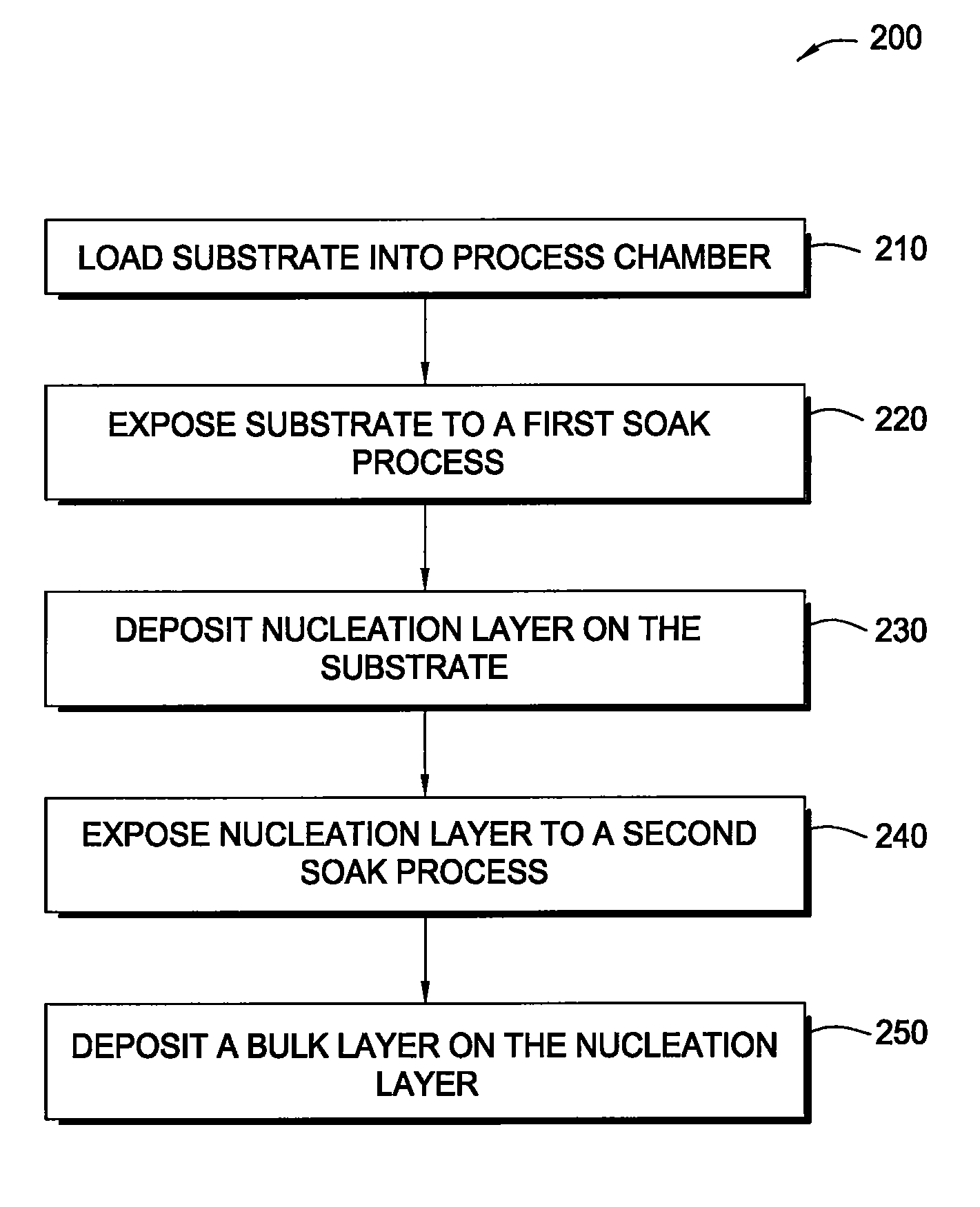
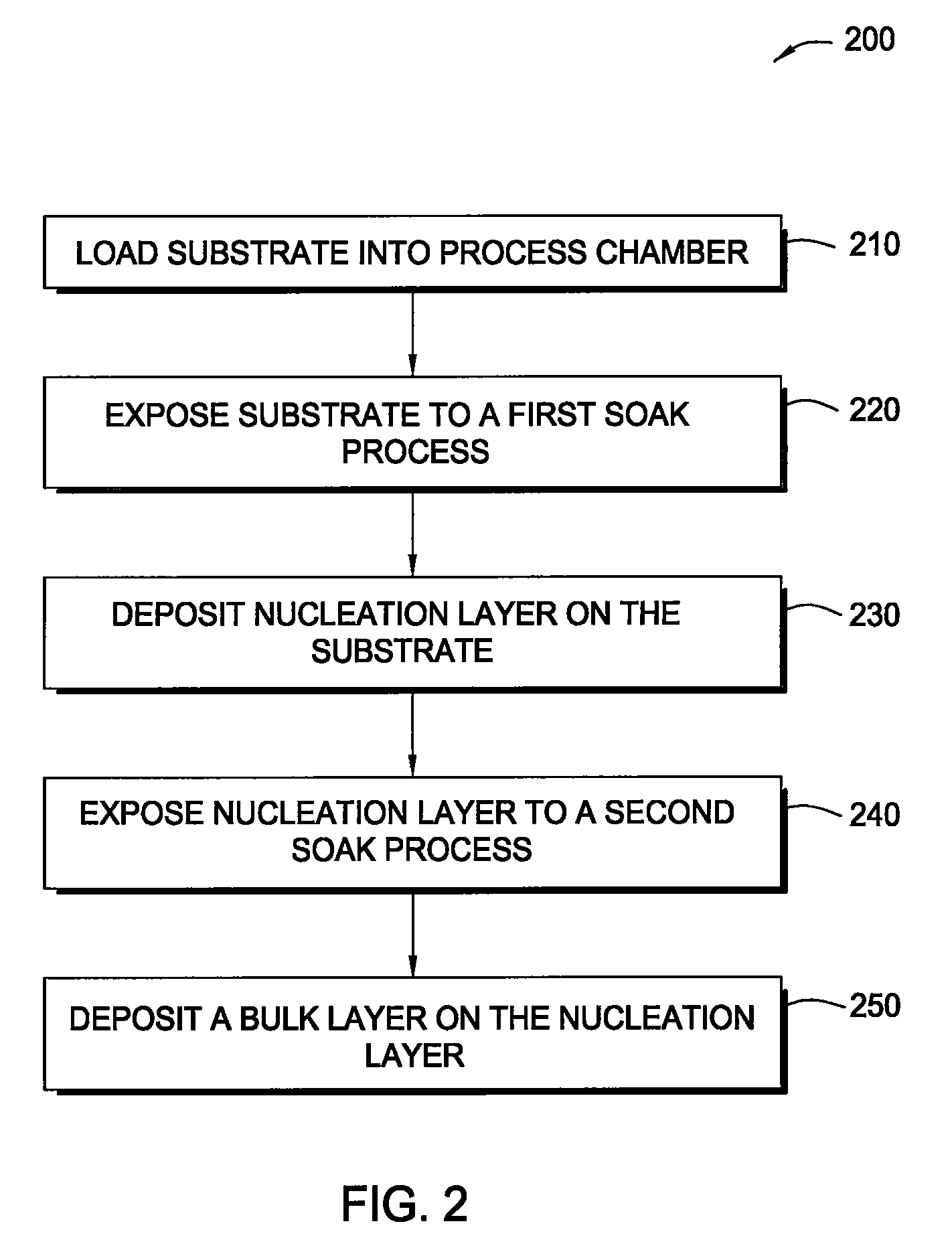
[0088]The substrate was placed into a deposition chamber and exposed to a soak process under the following conditions:[0089]Reagent: B2H6;[0090]Pressure: about 15 Torr;[0091]Temperature: about 375° C.;[0092]Flow rates: about 200 sccm of 5% B2H6 in N2 and about 8,000 sccm of H2;[0093]Hydrogen / hydride flow rate ratio: about 800:1; and[0094]Duration: about 10 seconds.

[0095]Next, a tungsten nucleation layer was formed on the barrier layer in the deposition chamber from the previous soak process using a pulsed-CVD process under the following conditions:[0096]Reagents: WF6, B2H6, and H2;[0097]Pressure: about 5 Torr;[0098]Temperature: about 375° C.;[0099]Flow rates: about 60 sccm of WF6, about 100 sccm of 5% B2H6 in N2, and about 6,000 sccm H2;[0100]Hydrogen / hydride flow rate ratio: about 1,200:1; and[0101]Pulse duration: about 1.5 seconds.

[0102]The pulsed-CVD process was continued until the nucleation layer had a thickness of about 25 Å. Thereafter, the substrate was kept in the depositio...

example 2

[0110]The substrate was placed into a deposition chamber and exposed to a soak process under the following conditions:[0111]Reagent: SiH4;[0112]Pressure: about 90 Torr;[0113]Temperature: about 400° C.;[0114]Flow rates: about 200 sccm of SiH4; and[0115]Duration: about 24 seconds.

[0116]Next, a tungsten nucleation layer was formed on the barrier layer in the deposition chamber from the previous soak process using a pulsed-CVD process under the following conditions:[0117]Reagents: WF6, B2H6, and H2;[0118]Pressure: about 5 Torr;[0119]Temperature: about 400° C.;[0120]Flow rates: about 60 sccm of WF6, about 100 sccm of 5% B2H6 in N2, and about 6,000 sccm of H2;[0121]Hydrogen / hydride flow rate ratio: about 1,200:1; and[0122]Pulse duration: about 1.5 seconds.

[0123]The pulsed-CVD process was continued until the nucleation layer had a thickness of about 25 Å. Thereafter, the substrate was kept in the deposition chamber and exposed to a second soak process under the following conditions:[0124]R...

example 3

[0131]The substrate was placed into a deposition chamber and exposed to a soak process under the following conditions:[0132]Reagent: SiH4;[0133]Pressure: about 90 Torr;[0134]Temperature: about 400° C.;[0135]Flow rates: about 200 sccm of SiH4; and[0136]Duration: about 24 seconds.

[0137]Next, a tungsten nucleation layer was formed on the barrier layer in the deposition chamber from the previous soak process using a pulsed-CVD process under the following conditions:[0138]Reagents: WF6 and SiH4;[0139]Pressure: about 5 Torr;[0140]Temperature: about 400° C.;[0141]Flow rates: about 60 sccm of WF6 and about 30 sccm of SiH4; and[0142]Pulse duration: about 1.5 seconds.

[0143]The pulsed-CVD process was continued until the nucleation layer had a thickness of about 20 Å. Thereafter, the substrate was kept in the deposition chamber and exposed to a second soak process under the following conditions:[0144]Reagent: B2H6 and H2;[0145]Pressure: about 90 Torr;[0146]Temperature: about 400° C.;[0147]Flow ...


PUM

PropertyMeasurementUnit
temperatureaaaaaaaaaa
timeaaaaaaaaaa
time periodaaaaaaaaaa

Abstract

Embodiments of the invention provide an improved process for depositing tungsten-containing materials. The process utilizes soak processes and vapor deposition processes, such as atomic layer deposition (ALD) to provide tungsten films having significantly improved surface uniformity and production level throughput. In one embodiment, a method for forming a tungsten-containing material on a substrate is provided which includes positioning a substrate within a process chamber, wherein the substrate contains an underlayer disposed thereon, exposing the substrate sequentially to a tungsten precursor and a reducing gas to deposit a tungsten nucleation layer on the underlayer during an ALD process, wherein the reducing gas contains a hydrogen / hydride flow rate ratio of about 40:1, 100:1, 500:1, 800:1, 1,000:1, or greater, and depositing a tungsten bulk layer on the tungsten nucleation layer. The reducing gas contains a hydride compound, such as diborane, silane, or disilane.

Description

CROSS-REFERENCE TO RELATED APPLICATIONS[0001]This application claims benefit of U.S. Ser. No. 60 / 938,124, filed May 15, 2007, which is hereby incorporated by reference in its entirety. This application is also a continuation-in-part of U.S. Ser. No. 11 / 038,592, filed on Jan. 19, 2005, and issued as U.S. Pat. No. 7,405,158, which is hereby incorporated by reference in its entirety.BACKGROUND OF THE INVENTION[0002]1. Field of the Invention[0003]Embodiments of the invention relate to the processing of substrates, more particularly, to the deposition of tungsten layers on substrates using vapor deposition processes.[0004]2. Description of the Related Art[0005]The semiconductor processing industry, as well as other industries which utilize substrate processing techniques, continues to strive for larger production yields while increasing the uniformity of layers deposited on substrates having larger surface areas. These same factors in combination with new materials also provide higher in...

Claims


Application Information

Patent Timeline
Patent Type & Authority Patents(United States)
IPC IPC(8): H01L21/44
CPCC23C16/0281C23C16/08C23C16/14C23C16/45525H01L21/28556H01L21/28562H01L21/76855H01L21/76856H01L21/7687H01L21/76876H01L21/76877H01L21/76843H01L2221/1089
Inventor KHANDELWAL, AMITMOORTHY, MADHUGELATOS, AVGERINOG V.WU, KAI
Owner APPLIED MATERIALS INC
Why Eureka
Try Eureka