Method and apparatus for preparing rare earth sintered magnet

a rare earth, sintered magnet technology, applied in the direction of presses, manufacturing tools, magnetic bodies, etc., can solve the problems of reducing the yield of sintered magnets, warping or deformation of sintered bodies, cracking or fissures, etc., to achieve efficient preparation of sintered magnets and high yields

Active Publication Date: 2015-06-25
SHIN ETSU CHEM IND CO LTD
View PDF0 Cites 3 Cited by
  • Summary
  • Abstract
  • Description
  • Claims
  • Application Information

AI Technical Summary

Benefits of technology

[0020]The method is effective for preparing a rare earth sintered magnet of unique shape, typically C or D shape and of quality in a consistent manner and in high yields while preventing the sintered body

Problems solved by technology

In this case, if the mold cavity is fully filled with fine powder so that the upper surface of powder may be flush with the top of the die, the amount of powder fill in the cavity per height of a magnet product to be molded is non-uniform among horizontally spaced apart positions.
A problem arises when this compact is sintered.
Namely, due to a difference in shrinkage between different sites in the compact, the sintered body can be warped or deformed and at the worst, cracked or fissured.
These problems invit

Method used


Image

  • Method and apparatus for preparing rare earth sintered magnet
  • Method and apparatus for preparing rare earth sintered magnet
  • Method and apparatus for preparing rare earth sintered magnet

Examples


example 1

[0046]A neodymium-based magnet alloy consisting of 31.0 wt % Nd, 1.0 wt % Co, 1.0 wt % B, 0.2 wt % Al, 0.2 wt % Cu, and the balance of Fe was coarsely crushed by hydrogen decrepitation and finely milled on a jet mill, obtaining a fine powder having an average particle size of 3.0 μm.

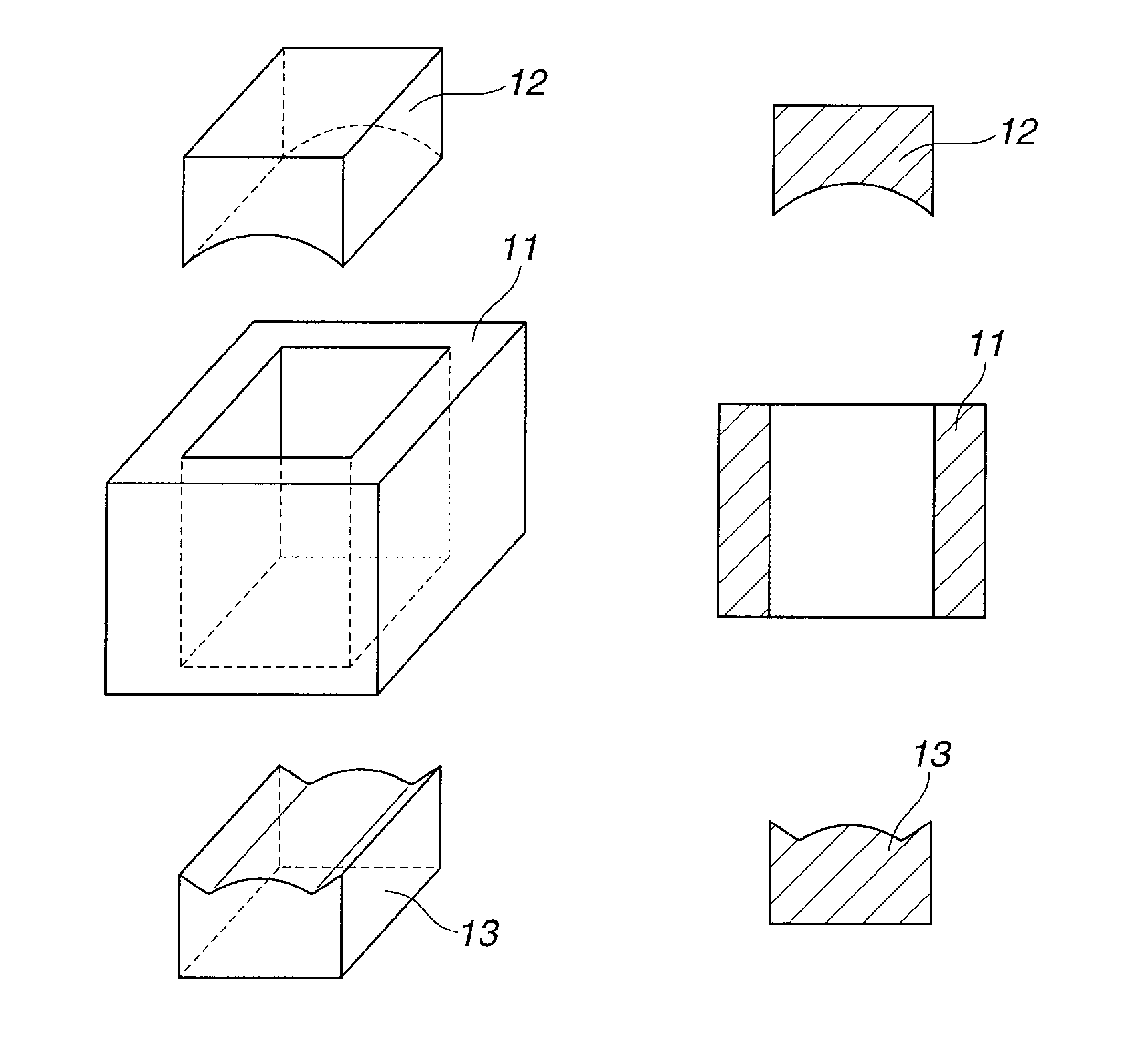
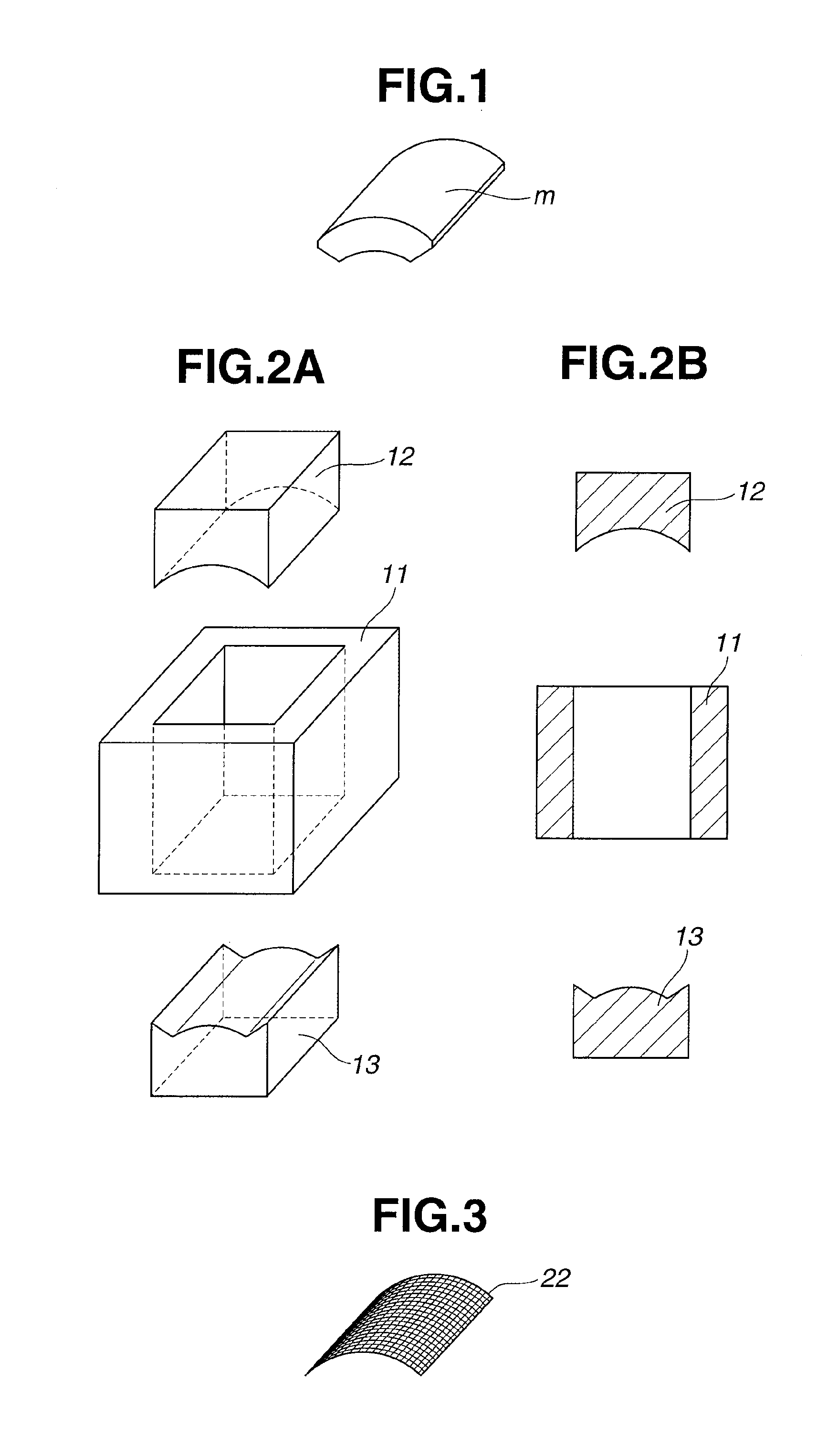
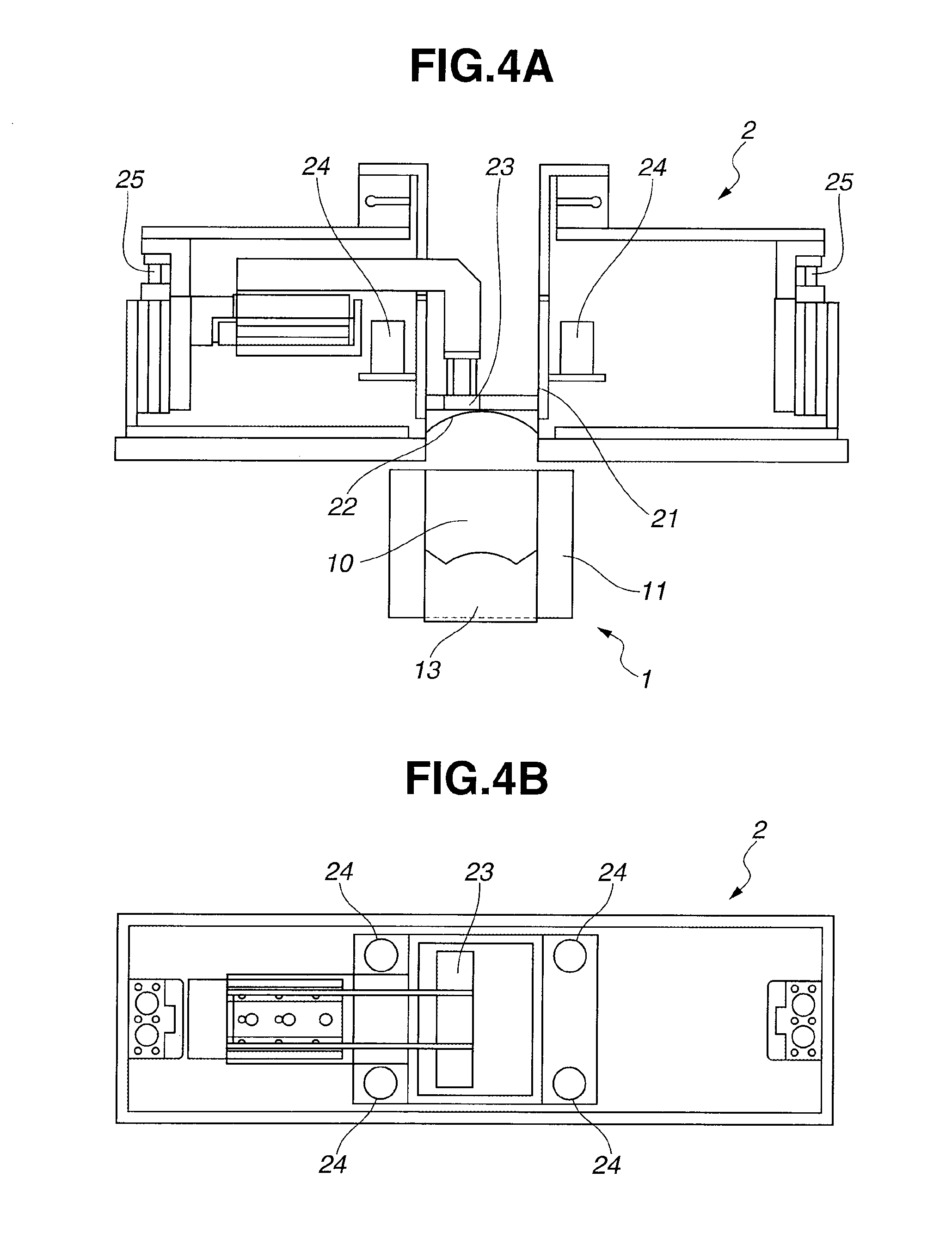
[0047]The fine powder was introduced in the shooter of the feeder shown in FIG. 4 and fed through a sieve of the shape of FIG. 3 with an opening of 10 mesh into a cavity defined by the die and the lower punch of the mold (size of the cavity: 40 mm width×70 mm height×50 mm length) configured as shown in FIG. 2. The piston vibrators having a frequency of 120 Hz and a vibromotive force of 100 N and pneumatic hammers having a frequency of 3 Hz and an amplitude of 5 mm were operated to apply vibration and vertical reciprocation to the shooter and sieve. The mold cavity was filled with the alloy powder to its full extent. The upper surface of the alloy powder fill was a curved surface of arcuate arch shape cor...

examples 2 to 4

[0050]By the same procedure as in Example 1 except that a sieve having an opening of 6.5 mesh (Example 2), 12 mesh (Example 3) or 36 mesh (Example 4) was used and the frequency of pneumatic hammers was changed to 5 Hz, the alloy powder was fed into the mold cavity. Table 2 reports an average of the time taken until the mold cavity was filled with the alloy powder to the full extent. The upper surface of the alloy powder fill was a curved surface of arcuate arch shape corresponding to the shape of the sieve. Subsequently, the same procedure as in Example 1 was followed until 10 sintered magnets were obtained. Each of 10 sintered magnets was measured at a plurality of positions as shown in FIG. 5 for dimensions, with their average and standard deviation (S.D.) computed, and inspected for crack or fissure. The results are shown in Table 2.

TABLE 2FillingAverage dimension (mm)Crack / time (s)uvwabcxyzfissureExample 21039.9440.1339.8021.0420.9721.0050.0149.7750.181 / 10S.D. 0.111S.D. 0.066S.D...


PUM

PropertyMeasurementUnit
Lengthaaaaaaaaaa
Forceaaaaaaaaaa
Frequencyaaaaaaaaaa

Abstract

A mold comprising a die, an upper punch, and a lower punch, the pressure surface of one or both of the upper and lower punches being shaped non-planar, a cavity being defined between the die and the lower punch, is combined with a feeder including a shooter provided with a main sieve at its lower end port, the main sieve having a sifting surface of substantially the same non-planar shape as the pressure surface. A rare earth sintered magnet is prepared by feeding an alloy powder into the cavity through the shooter and sieve while applying weak vibration and vertical reciprocation to the shooter, applying a uniaxial pressure to the alloy powder fill in the cavity under a magnetic field to form a precursor, and heat treating the precursor.

Description

CROSS-REFERENCE TO RELATED APPLICATION[0001]This non-provisional application claims priority under 35 U.S.C. §119(a) on Patent Application No. 2013-265256 filed in Japan on Dec. 24, 2013, the entire contents of which are hereby incorporated by reference.TECHNICAL FIELD[0002]This invention relates to a method and apparatus for preparing a rare earth sintered magnet, and more particularly, to a method for preparing a rare earth sintered magnet of unique shape, typically C or D shape by feeding an alloy powder to a mold, filling the mold cavity with the powder, and molding the powder under a magnetic field.BACKGROUND ART[0003]Nowadays, by virtue of their superior magnetic properties, rare earth sintered magnets, typically neodymium-based magnets are widely used in motors, sensors and other devices to be mounted in hard disks, air conditioners, hybrid vehicles, and the like.[0004]In general, rare earth sintered magnets are prepared by powder metallurgy as follows. First, raw materials a...

Claims


Application Information

Patent Timeline
IPC IPC(8): H01F41/02B22F5/00B22F3/00B22F1/00H01F1/053B22F3/12
CPCH01F41/0266H01F1/0536B22F5/00B22F3/003B22F1/00B22F3/12B22F3/03B22F3/02B22F2999/00C22C2202/02H01F1/0577B30B15/302H01F41/0273B22F2202/05B22F3/004B22F2202/01
Inventor KITAGAWA, MITSUOSAKAKI, KAZUAKI
Owner SHIN ETSU CHEM IND CO LTD
Why Eureka
Try Eureka