Fiber reinforced composite material structure, composite material molded body using the same, and manufacturing method therefor

a composite material and fiber reinforced technology, applied in the direction of other domestic objects, woodworking apparatus, transportation and packaging, etc., can solve the problems of affecting the light weight property and thin thickness property of the product, affecting the appearance quality of the product, and affecting the light weight property and thin thickness property, so as to achieve sufficient rigidity, reduce the effect of weight and reduction of thickness

Active Publication Date: 2015-07-02
MITSUBISHI CHEM CORP
View PDF2 Cites 17 Cited by
  • Summary
  • Abstract
  • Description
  • Claims
  • Application Information

AI Technical Summary

Benefits of technology

[0028]The fiber reinforced composite material structure according to the first aspect of the present invention may realize a reduction in thickness and a reduction in weight while maintaining sufficient rigidity and decreasing the amount of the adhesive used to adhere the surface material to the top faces of the convex portions of the thin sheet. Further, the fiber reinforced composite material structure according to the first aspect of the present invention may have an excellent bonding strength to the resin structure and may provide a composite material molded body of the second aspect of the present invention. The composite material molded body according to the second aspect of the present invention may be appropriately used as a casing of the electric / electronic device such as a personal computer. Further, the composite material molded body may be also used in aircraft parts, automobile parts, building products, household electrical appliances, and medical instruments.
[0029]Further, the third aspect of the present invention is the manufacturing method for the composite material molded body.

Problems solved by technology

Particularly, in the case that, when a load is applied to the casing of such a device from the outside thereof, a part of the casing is bent to thereby and come into contact with the inner component, the inner component or the casing may be damaged.
As a result, the quality of the product appearance is obtained only to a limited degree.
However, placing the core layer base which is formed of a soft material between the surface layer bases impede the light weight property and the thin thickness property.
In the case where the flowability of the resin is low or the injection pressure may not be increased during the injection-molding, the convex shape of the resin structure is not sufficiently inserted into the core layer base, and hence the sufficient bonding strength between the plate member and the resin structure is hard to obtain.

Method used


Image

  • Fiber reinforced composite material structure, composite material molded body using the same, and manufacturing method therefor
  • Fiber reinforced composite material structure, composite material molded body using the same, and manufacturing method therefor
  • Fiber reinforced composite material structure, composite material molded body using the same, and manufacturing method therefor

Examples


example 1

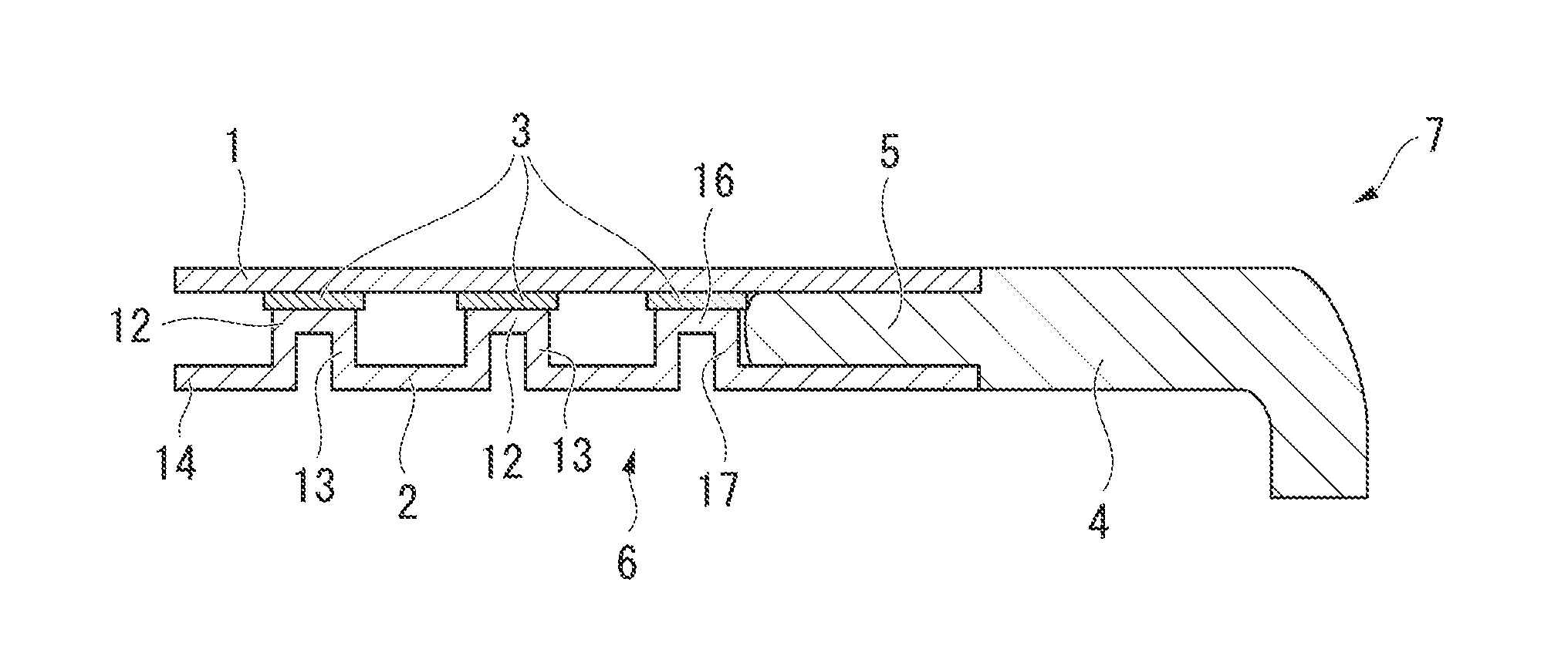
[0123]In the example, a unidirectional prepreg manufactured by Mitsubishi Rayon Co., Ltd. and having a product name of TR390E125S (an epoxy resin #390 (manufactured by Mitsubishi Rayon Co., Ltd.) as a thermosetting resin and a carbon fiber as a reinforcing fiber (manufactured by Mitsubishi Rayon Co., Ltd. and having a product name of TR50S)) was used.

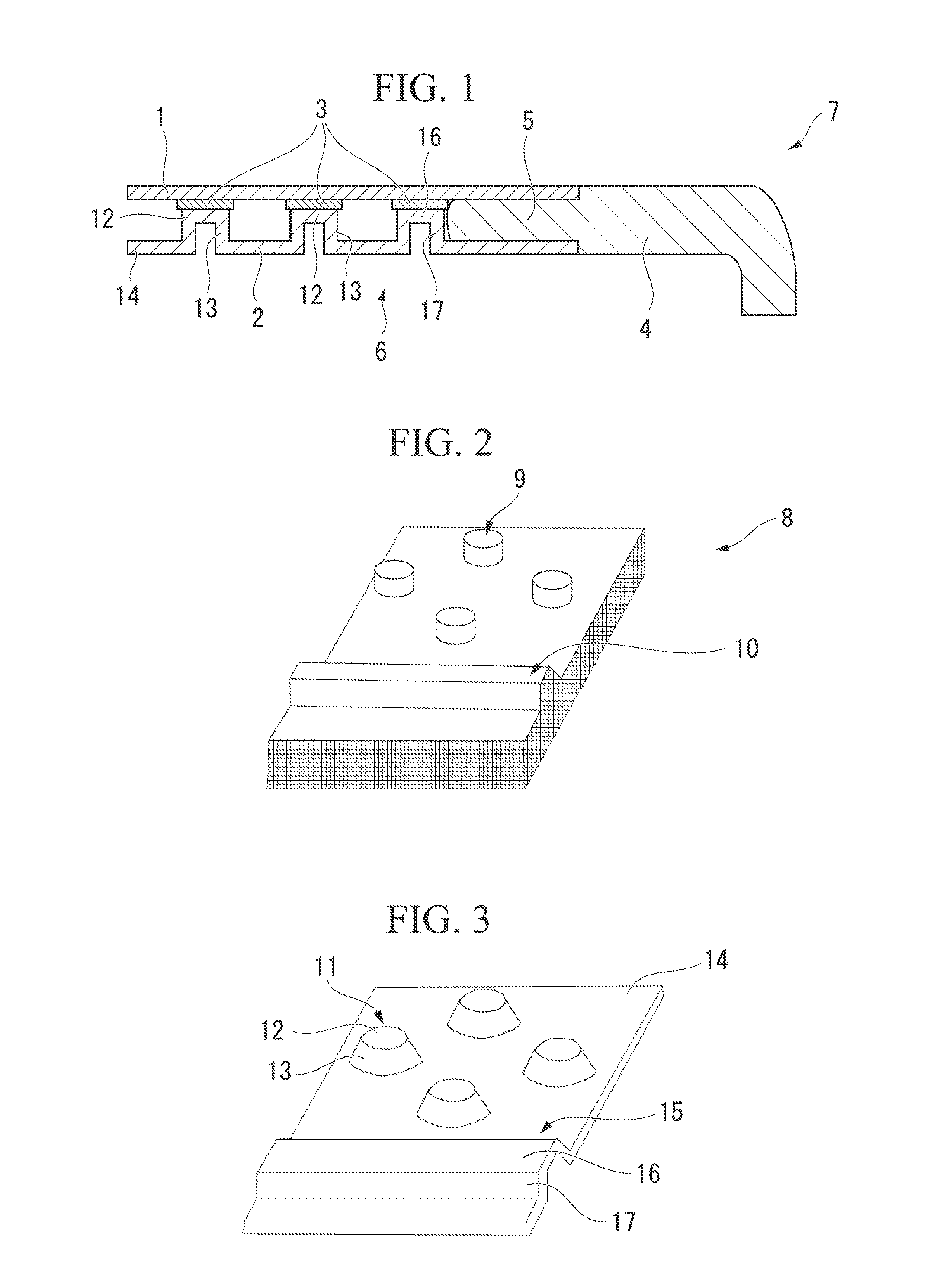
[0124]First, a laminate having the four layers of unidirectional prepreg (the unidirectional sheet) laminated at the angles of 0°, 90°, 90°, and 0° was disposed on the surface of the thin sheet lower die 8 including the protrusions to form the convex portions 11 of the thin sheet 2. Subsequently, the die was closed with the upper die having the recesses corresponding to the protrusions of the lower die 8, and the prepreg laminate was pressed for 5 minutes at the pressure of 8 MPa while being heated at 140° C. using the lower die 8 and the upper die so as to integrally cure the prepreg laminate. After the compression molding, the die was...

example 2

[0131]In the examples below, computer simulations were performed by referring to the result of Example 1.

[0132]“Femap with NX Nastran” was used as the simulation software, and the constrain condition was set as a simple support.

[0133]The thin sheet 2 and the surface material 1 of the example was molded in a manner such that a unidirectional prepreg manufactured by Mitsubishi Rayon Co., Ltd. and having a product name of TR390E125S (epoxy resin #390 (manufactured by Mitsubishi Rayon Co., Ltd.) as thermosetting resin and a carbon fiber (manufactured by Mitsubishi Rayon Co., Ltd. and having a product name of TR50S) as reinforcing fiber) was laminated as three layers as [0° / 90° / 0°], and the laminate was pressed and cured for 5 minutes at the pressure of 8 MPa while being heated at 140° C.

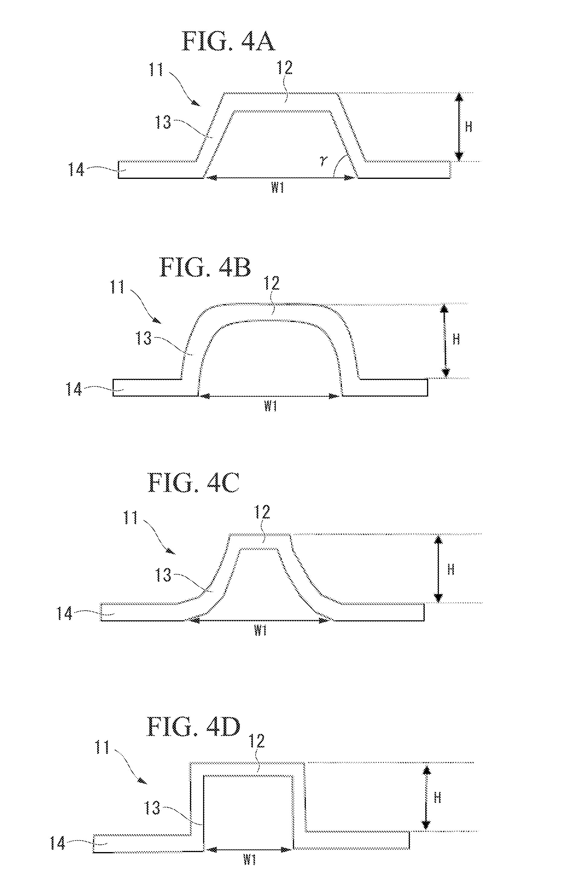
[0134]As the thin sheet 2, a molded sheet is used which has a longitudinal width of 200 mm and a lateral width of 300 mm and in which the columnar convex portions 11 each having a diameter of 5.0 mm are ...

example 3

[0138]The thickness and the weight of the structure of this example are set to be the same as those of the sandwich structure of Comparative Example 2. A structure having a thickness of 1.35 mm and a mass of 74.4 g is obtained by setting the height H of the columnar convex portions 11 to be 0.535 mm and setting the thickness of each of the layers forming the laminate to be 0.119 mm using the same method as Example 2.

[0139]The maximum bending displacement becomes 2.98 mm by the same bending test of the structures that of Example 2. Here, the bending displacement and the rigidity are the same as those of Comparative Example 2.


PUM

PropertyMeasurementUnit
overlap lengthaaaaaaaaaa
angleaaaaaaaaaa
angleaaaaaaaaaa

Abstract

A fiber reinforced composite material structure comprises a thin sheet that includes a first surface and a plurality of convex portions which protrude and are regularly arranged on the first surface and each of which includes a top face; and a surface material that includes a second surface and is bonded to the top faces on the second surface.

Description

TECHNICAL FIELD[0001]The present invention relates to a fiber reinforced composite material structure which is excellent in a light weight property, a thin thickness property, and rigidity. Specifically, the fiber reinforced composite material structure of the present invention is particularly excellent in the light weight property and the thin thickness property by a configuration in which a surface material formed of continuous reinforcing fibers and a matrix resin is bonded to one surface of a thin sheet formed of continuous reinforcing fibers and a matrix resin.[0002]The present application claims priority of Japanese Patent Application No. 2012-159553 filed on Jul. 18, 2012 and Japanese Patent Application No. 2013-081019 filed on Apr. 9, 2013, the entire contents of which are hereby incorporated by reference.BACKGROUND ART[0003]Since fiber reinforced plastic composite material (hereinafter, referred to as “FRP”) is light in weight and high in strength and rigidity, the FRP is w...

Claims


Application Information

Patent Timeline
Patent Type & Authority Applications(United States)
IPC IPC(8): B32B3/28B32B7/12B29C45/14
CPCB32B3/28B29C45/14508B32B7/12B32B2260/046B29L2009/00B32B2262/101B29C2045/14532B29C45/14336B29C45/14811B29C65/02B29C65/483B29C65/54B29C65/542B29C65/823B29C66/1122B29C66/21B29C66/234B29C66/438B29C66/71B29C66/721B29C66/7212B29C66/72141B29C66/7392B29C66/7394B29C66/834B29L2007/002B32B3/30B32B2260/023B32B2262/0253B32B2262/0269B32B2262/10B32B2262/103B32B2262/106B32B2305/076Y10T428/24628Y10T428/24661B29K2307/04B29K2309/08B29K2081/04B29K2079/08B29K2077/00B29K2071/12B29K2069/00B29K2067/06B29K2063/00B29K2061/04B29K2031/00
Inventor TAKANO, TSUNEOKAZEHAYA, YUUJINISHIMURA, MITSUSHIMAEDA, AKIHIRO
Owner MITSUBISHI CHEM CORP
Why Eureka
Try Eureka