
Direct coal liquefaction process

a technology of liquefaction process and coal, which is applied in the petroleum industry, liquid hydrocarbon mixture production, etc., can solve the problems of large-scale liquefaction of coal, low thermal efficiency of indirect coal-to-liquid conversion methods, and high cosub>2 /sub>emission, so as to reduce energy consumption, reduce the rate of coal liquefaction, and increase the effect of recycling

Inactive Publication Date: 2015-07-09
ACCELERGY CORP
View PDF7 Cites 3 Cited by
  • Summary
  • Abstract
  • Description
  • Claims
  • Application Information

AI Technical Summary

Benefits of technology

The patent is about a new process for liquefying coal using a recycled stream of product and a non-donor stream. This process has several technical effects. Firstly, the ratio of the recycled stream to coal in the process can be increased without reducing the flow rate of the recycled stream or the fresh coal. This means that less coal is needed, saving money and reducing energy requirements. Secondly, the process can efficiently liquefy even coals with high inertinite content, which was previously thought to be a limitation for some liquefaction methods. The process also operates with a lower gas hold-up, meaning it can achieve higher thermal efficiency. Lastly, the process does not require a hydrotreater to treat the donor solvent, further reducing complexity and cost. Overall, the new process provides a more efficient, cost-effective way to liquefy coal.

Problems solved by technology

A number of problems have hampered widespread liquefaction of coal, however, including the relatively low thermal efficiency of indirect coal-to-liquids (CTL) conversion methods, such as Fischer Tropsch (FT) synthesis and methanol-to-liquids (MTL) conversion, and concerns about CO2 emissions.
Thus, addition of an external solvent hydrotreater increases the required investment and decreases thermal efficiency.
In addition, the hydrotreating reduces the viscosity and lowers the aromatics content of the solvent, which reduces its ability to suspend ash in the slurry and its compatibility with coal.
The reduction in ability to suspend ash results in an increased likelihood of solids buildup, deposits, or plugging of high pressure feed pumps, transfer lines, heat exchangers, furnace tubes, and reactors.
Therefore, use of such donor solvents results in higher gas hold-up in the liquefaction reactor in order to maintain the solids in the slurry in suspension, which in turn, requires a large reactor volume to achieve adequate coal residence time in the reactor.
Because hydrotreaters are expensive, require energy for recycling gas, and use the heat of reaction less efficiently, DCL reactor systems have been designed to minimize the amount of donor solvent recycle.
Because of the high liquid recycle in ebullated bed reactors, the reactors are fully back-mixed which results in an increase in reactor volume versus a plug flow reactor.
A further issue limiting the application of DCL methods is that lower quality coals having inertinite content much higher than about 12% have been considered unsuitable for use as a DCL feed stock.
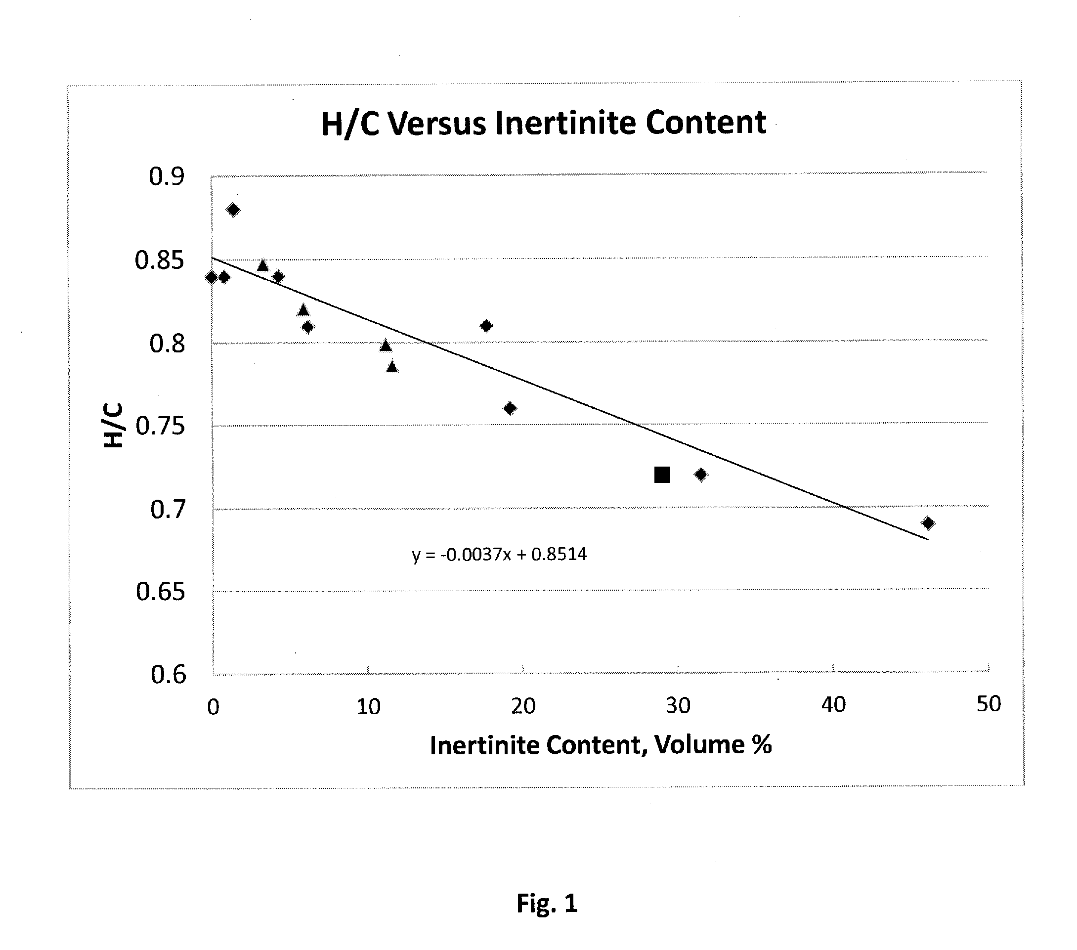
Many of these coals, such as that in the Ordos basin in China (1,2,3), have inertinite content of more than 25% and a low ratio of atomic hydrogen to carbon (H / C) and have historically been unacceptably more difficult to liquefy by DCL than higher quality coals that have a high vitrinite content.
He concluded that high inertinite coals, such as found in the Ordos Basin, are not suitable for direct liquefaction.
This high gas hold-up and corresponding lower solid and liquid hold-up results in an increase in liquefaction reactor volume required to achieve a given coal residence time and coal conversion to liquid products.

Method used


Image

  • Direct coal liquefaction process
  • Direct coal liquefaction process

Examples


example

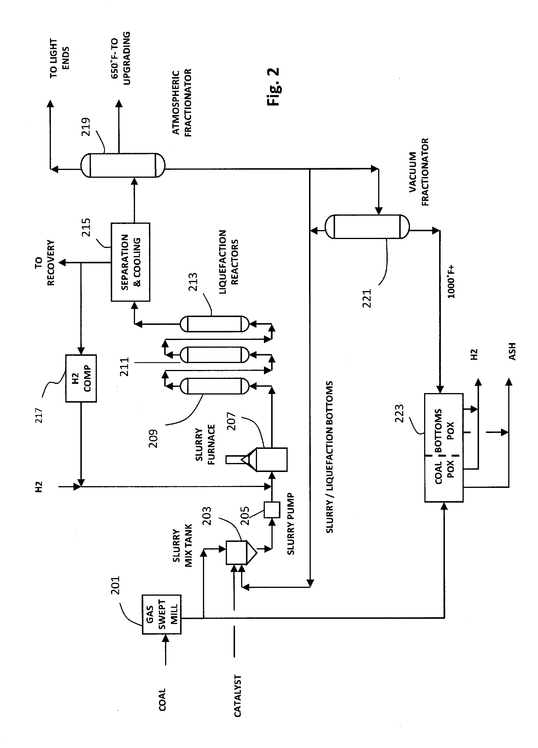
[0040]The process of the invention was run in the same 0.1 t / d pilot plant used in the runs described by Wasaka. Modifications were made to the pilot plant to the slurry mix tank, pumps, slurry reactors, microcatalyst (moly) addition, and 600 to 700° F.+ recycle. Compared to Wasaka's pilot plant operations, slurry feed rate was increased to 10 to 12 kg / hour and gas rate was reduced by a factor of 2 to 4. During the pilot plant operation, the reactors did not experience solids buildup or reactor deposits. The coal used in this example is shown as the square symbol in the chart of FIG. 1 and is therefore consistent with overall trend of H / C versus inertinite content.

[0041]Oil yield at a 1.5 / 1 ratio of non-donor 650° F.+(343° C.) recycle stream to coal was 44.6 wt % (MAF basis) When the 650° F.+ stream rate was increased to 3 / 1 at a low H2 feed rate of 0.73 Nm3 / kg of slurry, the C5+ / 371° C. (C5 / 650° F.) yield increased to 66.4 wt %. This is substantially higher than observed with an ir...


PUM


Abstract

A direct coal liquefaction method and apparatus in which the feed coal is mixed with a recycled 600° F.+ non-donor stream in which the ratio of coal to said stream is at least 1.5:1 on a moisture free basis to form an input slurry to a DCL reactor. Hydrogen containing treat gas is supplied to the reactor. 1000° F.− bottoms from the reactor are recycled as part of the 600° F.+ non-donor stream. 1000° F.+ bottoms from the reactor are gasified in a PDX unit to provide hydrogen for the DCL reaction. The ratio of recycled bottoms to feed coal is between 1:0.5 and 1:1.5.

Description

FIELD OF THE INVENTION[0001]The present invention relates to a direct coal liquefaction process capable of producing gasoline, jet fuel, or diesel from high inertinite content coal at high thermal efficiency.BACKGROUND OF THE INVENTION[0002]Increases in the cost of petroleum and concerns about future shortages have led to increased interest in the use as a fuel source of the vast, easily accessible deposits of coal that exist in several parts of the world. Various processes have been proposed for converting coal to liquid and gaseous fuel products including gasoline, diesel fuel, aviation turbine fuel and heating oil, and, in some cases, to other products such as lubricants and chemicals. A number of problems have hampered widespread liquefaction of coal, however, including the relatively low thermal efficiency of indirect coal-to-liquids (CTL) conversion methods, such as Fischer Tropsch (FT) synthesis and methanol-to-liquids (MTL) conversion, and concerns about CO2 emissions. Direc...

Claims


Application Information

Patent Timeline
IPC IPC(8): C10G1/06
CPCC10G1/06C10G1/086
Inventor BAUMAN, RICHARD F.MAA, PETER S.
Owner ACCELERGY CORP
Learn More