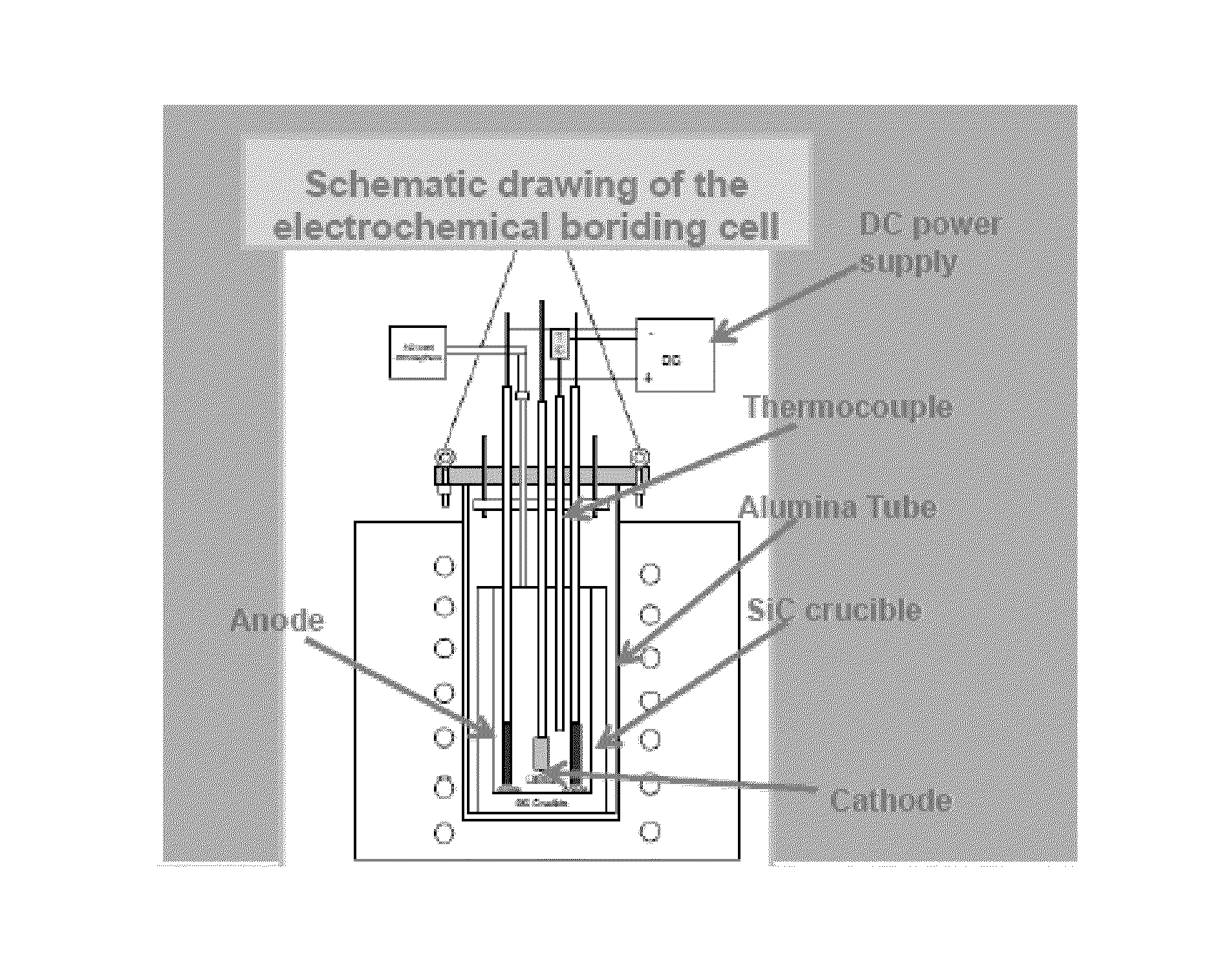
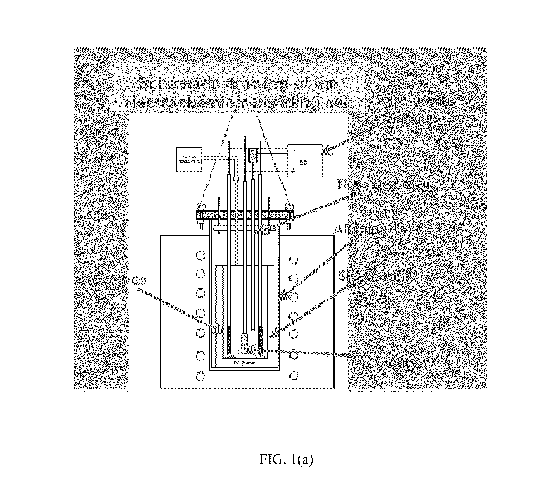
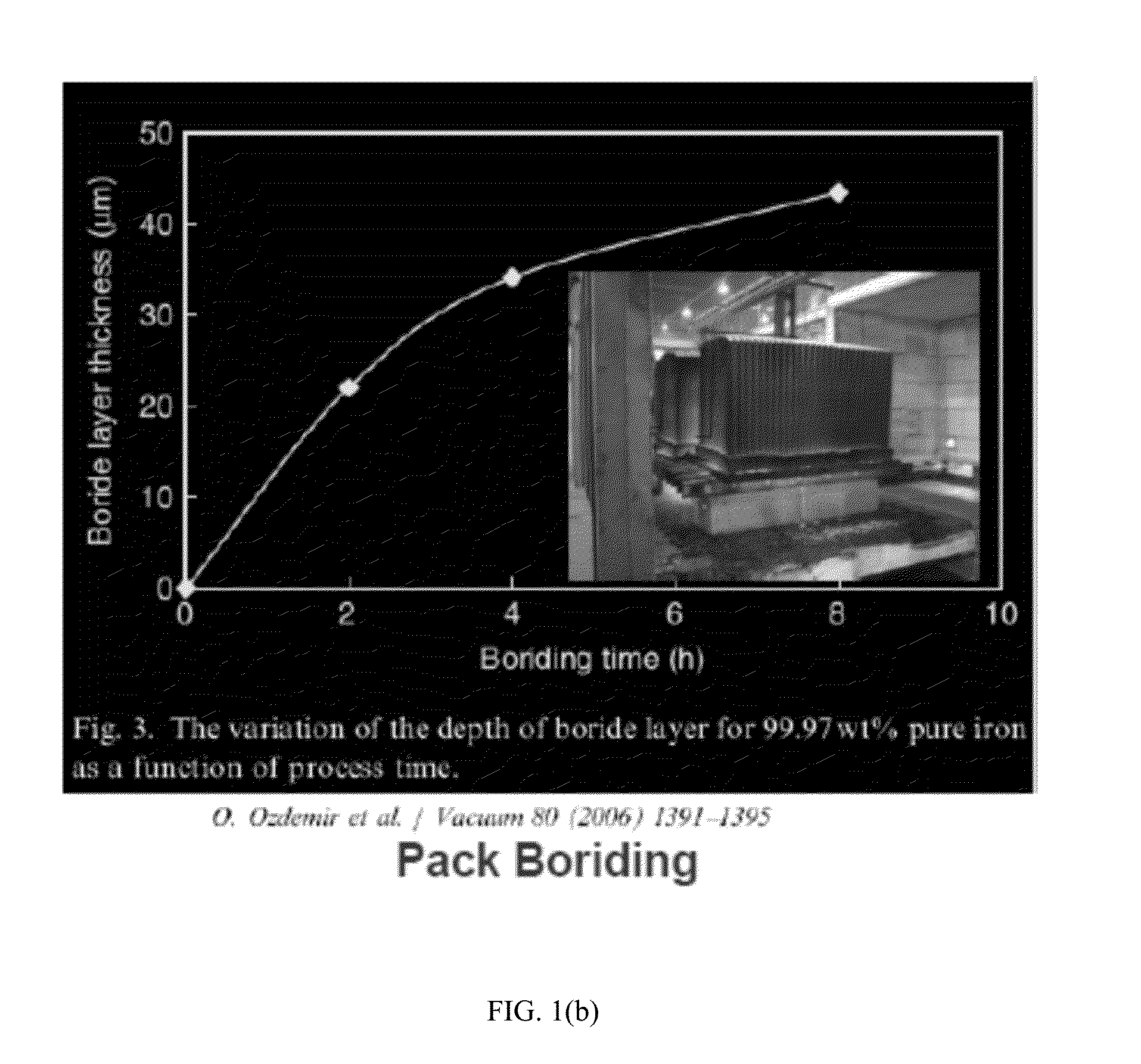
Method for Ultra-Fast Boriding

a technology of ultra-fast boriding and boriding parts, which is applied in the direction of natural mineral layered products, coatings, chemistry apparatuses and processes, etc., can solve the problems of difficult to meet the requirements of existing tool materials and coatings, and achieve the effects of improving the operating/and parts, improving the service life and performance of tools, and improving the service life and performan

Active Publication Date: 2015-07-23
UCHICAGO ARGONNE LLC
View PDF3 Cites 2 Cited by
  • Summary
  • Abstract
  • Description
  • Claims
  • Application Information

AI Technical Summary

Benefits of technology

[0012]Ultra-fast boriding of metal-cutting and forming tools is provided to increase commercial production rate as well as improve tool and / and part operating lifetime and performance. In particular, the invention is directed toward the boriding of cemented carbide based tool inserts like tungsten carbide (WC), W-alloys, and high-carbon, high-alloy steels, such as, high speed and D2 quality steels that are used in the manufacture of metal-cutting and forming tools. Ultra-fast boriding process produces very hard and thick layers on these materials and makes their surfaces very resistant to wear, oxidation and corrosion. Such treated tools and parts have much improved operating lifetime and performance. Boriding of WC inserts can potentially minimize or eliminate necessity of physical vapor deposition (PVD), or chemical vapor deposition (CVD) coating of these inserts or can be complimentary to such coating processes to achieve improved combined performance if applied sequentially. Boriding of WC tools or parts will create a much harder (up to 3500 Vickers) tungsten boride layer on the surface of the treated material. Boride layers are also chemically very stable at high temperatures which can create additional benefits since cutting operations create very high temperatures in cutting wear of cutting tool as well.

Problems solved by technology

Boriding tools can also be used in dry Al and Mg machining (which is very difficult with existing tool materials and coatings).

Method used


Image

  • Method for Ultra-Fast Boriding
  • Method for Ultra-Fast Boriding
  • Method for Ultra-Fast Boriding

Examples


example i

[0038]Wear testing was performed for a borided W—Re alloy against a ⅜″ diameter wear ball of 52100 steel at room temperature, and ball rotation rate of 50 rpm at a load of 1N. As shown in FIGS. 10(a)-10(c), the wear surface shows no abrasion of the wear surface; and FIG. 10(d) shows coefficient of friction versus time for a 1 h test.

[0039]FIGS. 11(a)-11(d) confirm the layer depositions on the substrate and that virtually no wear occurred to the borided surface.

example ii

[0040]Wear testing was performed for a borided W—Re alloy against a ⅜″ diameter alumina ball for the same operating conditions as Example I. As shown in FIGS. 12(a)-12(c) the wear surface shows no abrasion of the borided surface and FIG. 12(d) shows coefficient of friction versus time for the 1 h test. FIGS. 13(a)-13(d) show an SEM image of the surface of the borided W—Re surface after the test shown in FIGS. 12(a)-12(c). FIG. 13(b) shows a cross-section of the tested, borided W—Re surface; and FIG. 13(c) shows a profilometer scan of the cross-section of FIG. 13(b). FIG. 13(d) shows a profilometer 3D scan image from the scan of FIG. 13(c).


PUM

PropertyMeasurementUnit
temperatureaaaaaaaaaa
depthsaaaaaaaaaa

Abstract

An article of manufacture and method of forming a borided material. An electrochemical cell is used to process a substrate to deposit a plurality of borided layers on the substrate. The plurality of layers are co-deposited such that a refractory metal boride layer is disposed on a substrate and a rare earth metal boride conforming layer is disposed on the refractory metal boride layer.

Description

STATEMENT OF GOVERNMENT INTEREST[0001]The U.S. Government has rights in the invention pursuant to Contract No. W-31-109-ENG-38 between the U.S. Government and the University of Chicago and / or pursuant to DE-AC-02-06 CHJ11357 between the U.S. Government and UChicago Argonne, LLC representing Argonne National Laboratory.FIELD OF THE INVENTION[0002]This invention relates to article and methods for manufacture for producing a borided materials by using an ultra-fast methodology. More particularly the invention relates to a method for ultra-fast manufacturing of borided metal-cutting and metal-forming tools to increase their operating lifetime, as well as provide improved performance. Further, the invention relates to the ultra-fast boriding of cemented carbide based tool components, such as WC, W-alloys and high carbon, high alloy steels use in metal cutting and metal forming tools.BACKGROUND OF THE INVENTION[0003]Most mechanical components used in a variety of rolling, rotating, or sli...

Claims


Application Information

Patent Timeline
Patent Type & Authority Applications(United States)
IPC IPC(8): C25D3/56
CPCC25D3/56C25D11/028C25D3/66
Inventor ERDEMIR, ALISISTA, VIVEKANANDKAHVECIOGLU, OZGENURERYILMAZ, OSMAN LEVENT
Owner UCHICAGO ARGONNE LLC
Why Eureka
Try Eureka