
Polarizing plate

a technology of polarizing plate and liquid crystal display device, which is applied in the direction of polarizing element, film/foil adhesive without carrier, instruments, etc., can solve the problems of degrading the optical characteristics of the polarizing plate, not easy to provide a polarizing plate that achieves the desired level of performance, and is generally susceptible to moisture, etc., to achieve enhanced cohesiveness and adhesive stability of pressure-sensitive adhesives, and prevent generation

Active Publication Date: 2015-07-23
LG CHEM LTD
View PDF15 Cites 12 Cited by
  • Summary
  • Abstract
  • Description
  • Claims
  • Application Information

AI Technical Summary

Benefits of technology

The patent describes a pressure-sensitive adhesive used in a polarizing plate used in LCD devices. The adhesive needs to have a specific range of elastic modulus, with an average elastic modulus of 700 MPa or less. This elastic modulus range prevents light leakage and ensures durability of the polarizing plate. The adhesive should also have a gel content of 80 wt % or more to achieve excellent durability under severe conditions, with an upper limit of about 99% or less.

Problems solved by technology

Since the polarizer is conventionally manufactured of a hydrophilic resin such as polyvinylalcohol, it is generally vulnerable to moisture.
In addition, since the polarizing plate is manufactured by an orientation process, contraction easily occurs under conditions of high humidity, which degrades optical characteristics of the polarizing plate.
However, it is not easy to provide a polarizing plate that achieves a desired level of performance without using a protective film.

Method used


Image

  • Polarizing plate
  • Polarizing plate
  • Polarizing plate

Examples


preparation example 1

Preparation of Acrylic Polymer (A)

[0166]90 parts by weight of n-butyl acrylate (n-BA), 12 parts by weight of methoxy ethyleneglycol acrylate (MEA) and 2 parts by weight of 2-hydroxyethyl acrylate (2-HEA) were put into a 1 L reaction vessel equipped with a cooling device to reflux a nitrogen gas and facilitate temperature control. Subsequently, 180 parts by weight of ethyl acetate (EAc) was put as a solvent into the reaction vessel and purged with the nitrogen gas for 60 minutes to remove oxygen. Afterward, the temperature was maintained at 60° C., 0.05 parts by weight of azobisisobutyronitrile (AIBN) was put as a reaction initiator into the reaction vessel, and the reaction was carried out for 8 hours. After the reaction, the reaction product was diluted with ethyl acetate (EAc), and thus an acrylic polymer (A) having a solid content of 30 wt %, a weight average molecular weight of 1,000,000, and a molecular weight distribution of 4.9 was prepared.

preparation example 2

Preparation of Acrylic Polymer (B)

[0167]An acrylic polymer was prepared by the same method as described in Preparation Example 1, except that 90 parts by weight of n-butyl acrylate (n-BA), 13 parts by weight of methoxy ethyleneglycol acrylate (MEA), 2 parts by weight of 2-hydroxyethyl acrylate (2-HEA), and 0.5 parts by weight of acrylic acid (AA) were put into the reaction vessel.

preparation example 3

Preparation of Acrylic Polymer (C)

[0168]An acrylic polymer was prepared by the same method as described in Preparation Example 1, except that 90 parts by weight of n-butyl acrylate (n-BA), 15 parts by weight of methoxy ethyleneglycol acrylate (MEA), and 2 parts by weight of 2-hydroxyethyl acrylate (2-HEA) were put into the reaction vessel.


PUM

PropertyMeasurementUnit
temperatureaaaaaaaaaa

Abstract

The present application relates to a polarizing plate and a liquid crystal display device. The polarizing plate which is thin and light, meets requirements for physical properties such as durability, moisture resistance, workability and light leakage inhibiting ability, and has an antistatic property, and the liquid crystal display device including the same may be provided.

Description

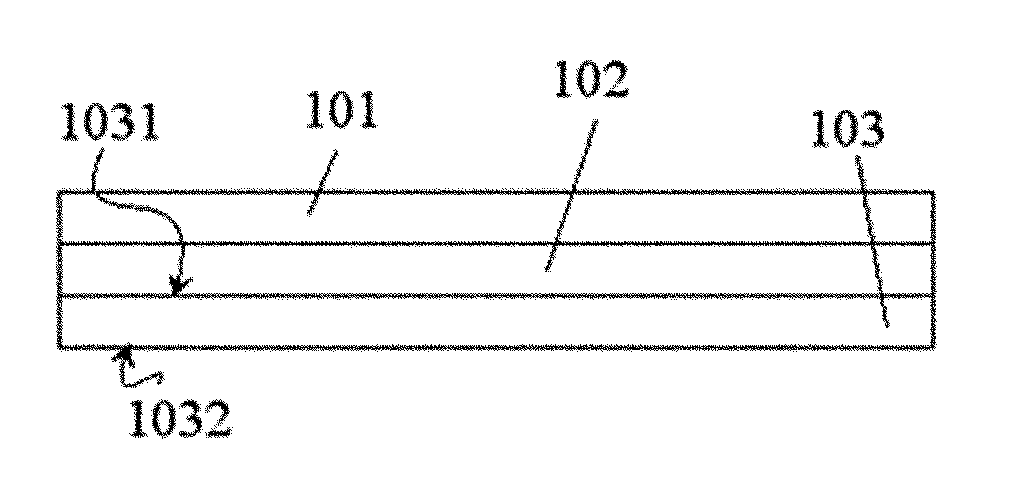
BACKGROUND[0001]1. Field of the Invention[0002]The present application relates to a polarizing plate and a liquid crystal display device.[0003]2. Discussion of Related Art[0004]A liquid crystal display (LCD) device is a display device that consumes less power, is formed as a thin planar display, and is applied in various fields.[0005]An LCD device includes a liquid crystal panel having liquid crystals interposed between transparent substrates, and a polarizing plate attached to both sides of the liquid crystal panel.[0006]The polarizing plate includes a polarizer exhibiting a polarizing function. Since the polarizer is conventionally manufactured of a hydrophilic resin such as polyvinylalcohol, it is generally vulnerable to moisture. In addition, since the polarizing plate is manufactured by an orientation process, contraction easily occurs under conditions of high humidity, which degrades optical characteristics of the polarizing plate. Accordingly, in a conventional polarizing pla...

Claims


Application Information

Patent Timeline
Patent Type & Authority Applications(United States)
IPC IPC(8): G02B5/30C09J133/14G02F1/1335C09J7/10
CPCG02B5/3025C09J133/14G02F1/133528C09J133/08C09J2203/318C09J2433/00G02F2202/28C09J7/10Y10T428/2891Y10T428/2848C09J133/04G02F2201/50C09J2301/312C09K2323/057C09K2323/035C09K2323/059C09K2323/031C09J7/385C09J7/22C09J7/40G02B5/3041G02B5/305C09J9/00G02F1/1335B32B2457/202G02B5/30G02F1/13G02B1/10
Inventor PARK, IN KYUKIM, NO MAHWANG, IN HOYOON, SUNG SOOKIM, MIN JOON
Owner LG CHEM LTD
Learn More