Transparent conductor and touch panel

a transparent conductor and touch panel technology, applied in the field of transparent conductors and touch panels, can solve the problems of difficult thermal annealing at a high temperature, difficult preparation of zn—sn—o oxide films or films, and difficult resistance of film substrates, etc., to achieve excellent storage reliability, clear display, and low surface resistance

Active Publication Date: 2015-07-23
TDK CORPARATION
View PDF4 Cites 11 Cited by
  • Summary
  • Abstract
  • Description
  • Claims
  • Application Information

AI Technical Summary

Benefits of technology

[0018]Such a touch panel includes the transparent conductor having the above-mentioned characteristics and thus achieves clear display and has excellent storage reliability.
[0019]The present invention can provide a transparent conductor having a low surface resistance and a hi

Problems solved by technology

In addition, film substrates are difficult to be thermally annealed at a high temperature.
On this account, the ITO film provided on a film substrate is difficult to have lower resistance while maintaining high transmittance.
The Zn—Sn—O oxide film or the

Method used


Image

  • Transparent conductor and touch panel
  • Transparent conductor and touch panel
  • Transparent conductor and touch panel

Examples


production example 1

Production of Transparent Conductor 101

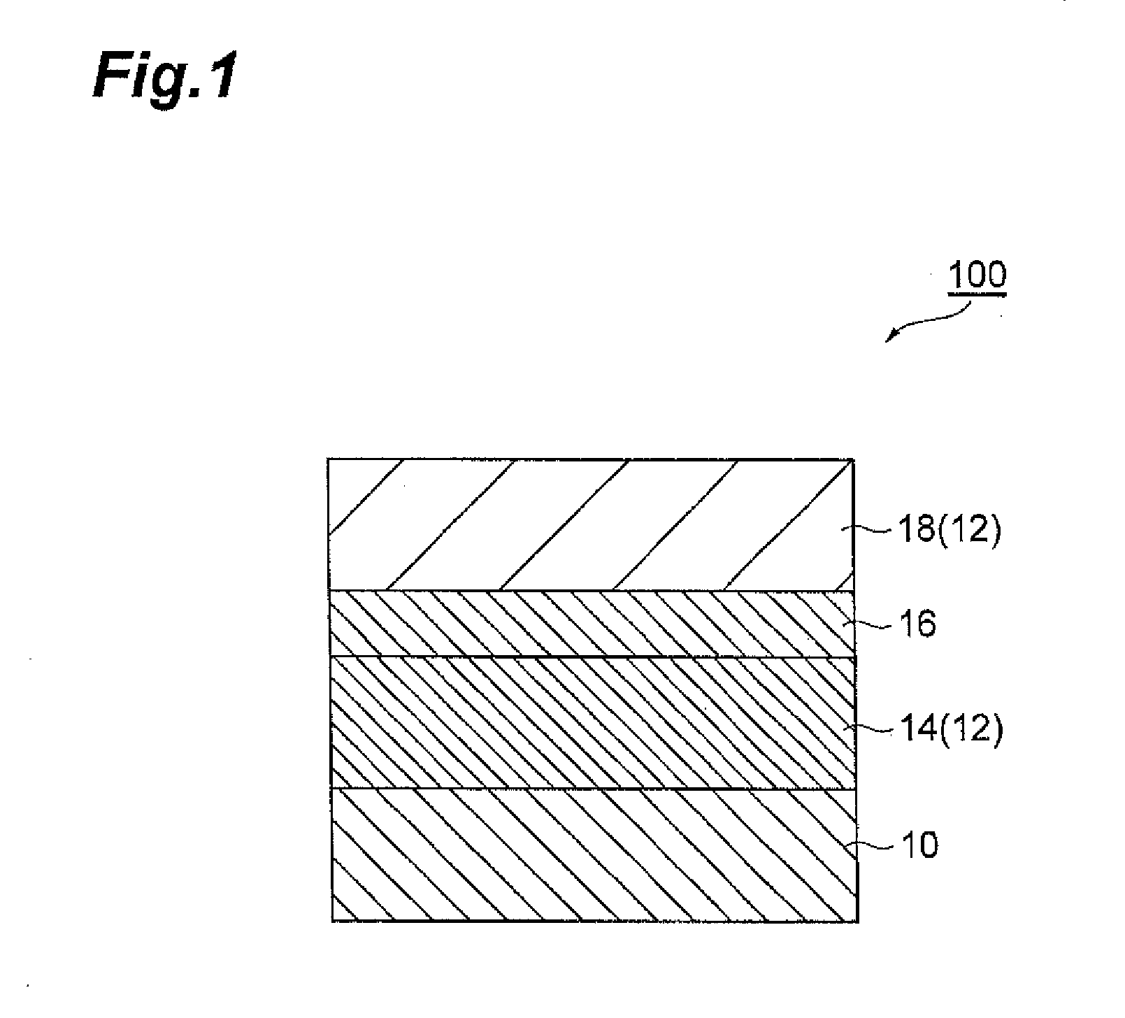
[0084]A transparent conductor 101 as shown in FIG. 3 was produced. The transparent conductor 101 had a multilayer structure in which a second hard coat layer 24, a transparent substrate 10, a first hard coat layer 22, a first metal oxide layer 14, a metal layer 16, and a second metal oxide layer 18 were stacked in this order. The transparent conductor 101 was produced by the following procedure.

[0085]A polyethylene terephthalate film (manufactured by Toray Industries Inc., product number: U48) having a thickness of 100 μm was prepared. This PET film was used as the transparent substrate 10. A coating material for forming the first hard coat layer 22 and the second hard coat layer 24 was prepared by the following procedure. First, the following raw materials were prepared.

[0086]Reactive group-modified colloidal silica (dispersion medium: propylene glycol monomethyl ether acetate, nonvolatile content: 40% by weight): 100 parts by weight

[0087]Dipe...

production example 2

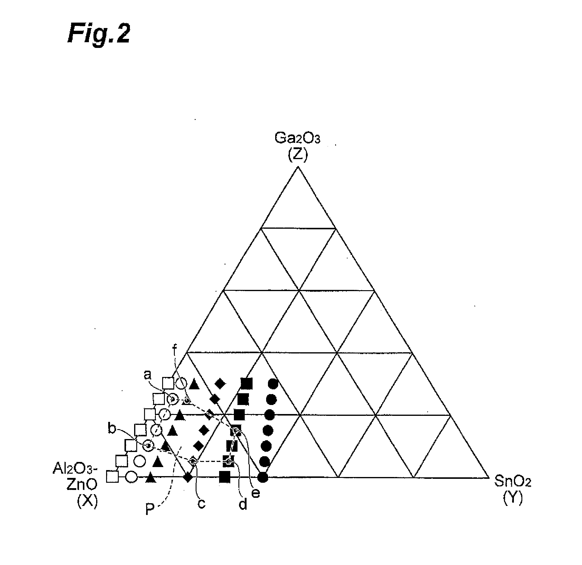
[0099]In the same manner as in Production Example 1, on the first hard coat layer 22, a first metal oxide layer 14, a metal layer 16, and a second metal oxide layer 18 were sequentially formed by DC magnetron sputtering, giving samples 8 to 14 of the transparent conductor 101. In Production Example 2, γ was changed in a range of 0 to 30% by mole where the Al2O3—ZnO—SnO2—Ga2O3 target had a composition ratio of [(Al2O3—ZnO)95(SnO2)5]100-γ(Ga2O3)γ. Here, the ratio of Al2O3, α, was fixed at 2% by mole.

[0100]The compositions of the first metal oxide layer 14 and the second metal oxide layer 18 in Production Example 2 are as shown in Table 2. The compositions of the first metal oxide layer 14 and the second metal oxide layer 18 in Production Example 2 are indicated with open circles in the ternary diagram of FIG. 2. Each sample in Production Example 2 was evaluated in the same manner as in Production Example 1. Table 2 shows the results.

TABLE 2Sample 8Sample 9Sample 10Sample 11Sample 12Sa...

production example 3

[0102]In the same manner as in Production Example 1, on the first hard coat layer 22, a first metal oxide layer 14, a metal layer 16, and a second metal oxide layer 18 were sequentially formed by DC magnetron sputtering, giving samples 15 to 21 of the transparent conductor 101. In Production Example 3, γ was changed in a range of 0 to 30% by mole where the Al2O3—ZnO—SnO2—Ga2O3 target had a composition ratio of [(Al2O3—ZnO)90(SnO2)10]100-γ(Ga2O3)γ. Here, the ratio of Al2O3, α, was fixed at 2% by mole.

[0103]The compositions of the first metal oxide layer 14 and the second metal oxide layer 18 in Production Example 3 are as shown in Table 3. The compositions of the first metal oxide layer 14 and the second metal oxide layer 18 in Production Example 3 are indicated with triangles in the ternary diagram of FIG. 2. Each sample in Production Example 3 was evaluated in the same manner as in Production Example 1. Table 3 shows the results.

TABLE 3Sample 15Sample 16Sample 17Sample 18Sample 19S...


PUM

PropertyMeasurementUnit
Percent by moleaaaaaaaaaa
Transparencyaaaaaaaaaa

Abstract

The transparent conductor includes a transparent substrate, a first metal oxide layer, a metal layer, and a second metal oxide layer laminated. At least one of the first and the second metal oxide layers contains four components of Al2O3, ZnO, SnO2, and Ga2O3. X, Y, and Z are within a region surrounded by line segments between point a, point b, point c, point d, point e, and point f, in terms of (X, Y, Z) coordinates shown in a ternary diagram in FIG. 2, or on the line segments where X is a total molar ratio of the Al2O3 and the ZnO, Y is a molar ratio of the SnO2, and Z is a molar ratio of the Ga2O3, relative to the total amount of the four components. A molar ratio of the Al2O3 relative to the total amount of the four components is 1.5 to 3.5% by mole.

Description

CROSS REFERENCE TO RELATED APPLICATIONS[0001]This application is based upon and claims the benefit of priority from Japanese Patent Application No. 2014-006919, filed on Jan. 17, 2014, the entire contents of which are incorporated herein by reference.BACKGROUND[0002]1. Field[0003]This disclosure relates to a transparent conductor and a touch panel including the conductor.[0004]2. Description of the Related Art[0005]Transparent conductors, which have transparency and electric conductivity, have been used as transparent electrodes for displays such as liquid crystal displays (LCDs), plasma display panels (PDPs), and electroluminescence (organic EL and inorganic EL) panels and for solar cells, for example. In addition, the transparent conductors have been also used for electromagnetic wave shielding films and infrared ray shielding films, for example.[0006]The transparent conductor is exemplified by ITO prepared by adding tin (Sn) to indium oxide (In2O3), GZO prepared by adding gallium...

Claims


Application Information

Patent Timeline
IPC IPC(8): G06F3/044G06F1/16
CPCG06F1/16G06F3/044C23C14/08C23C14/3414G06F3/0445G06F3/0446G06F3/0447
Inventor SHINGAI, HIROSHIFUJITA, MINORUOISHI, MASAHIRO
Owner TDK CORPARATION
Why Eureka
Try Eureka