Carbon dioxide reduction device and method for reducing carbon dioxide

a carbon dioxide and reduction device technology, applied in the direction of metal/metal-oxide/metal-hydroxide catalysts, physical/chemical process catalysts, instruments, etc., can solve the problem that the efficiency of reducing co2 /sub>by light energy to convert it into carbon compounds without the use of any external power source is not necessarily high enough, so as to reduce co2. , the effect of reducing co2

Inactive Publication Date: 2015-08-06
PANASONIC CORP
View PDF2 Cites 10 Cited by
  • Summary
  • Abstract
  • Description
  • Claims
  • Application Information

AI Technical Summary

Benefits of technology

[0020]The CO2 reduction device and the method for reducing CO2 of the present disclosure are the device and method for reducing CO2 by light energy, in which CO2 can be reduced without the use of any external power source and CO2 can be converted into carbon compounds with higher efficiency than conventional devices and methods.

Problems solved by technology

However, in conventional devices and methods, the efficiency of reducing CO2 by light energy to convert it into carbon compounds without the use of any external power source is not necessarily high enough.

Method used


Image

  • Carbon dioxide reduction device and method for reducing carbon dioxide
  • Carbon dioxide reduction device and method for reducing carbon dioxide
  • Carbon dioxide reduction device and method for reducing carbon dioxide

Examples


example 1

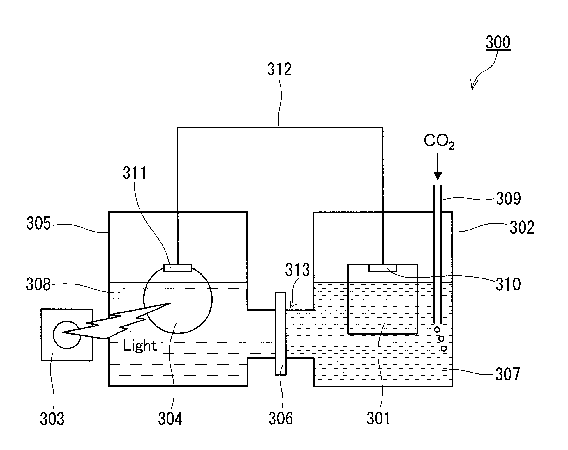
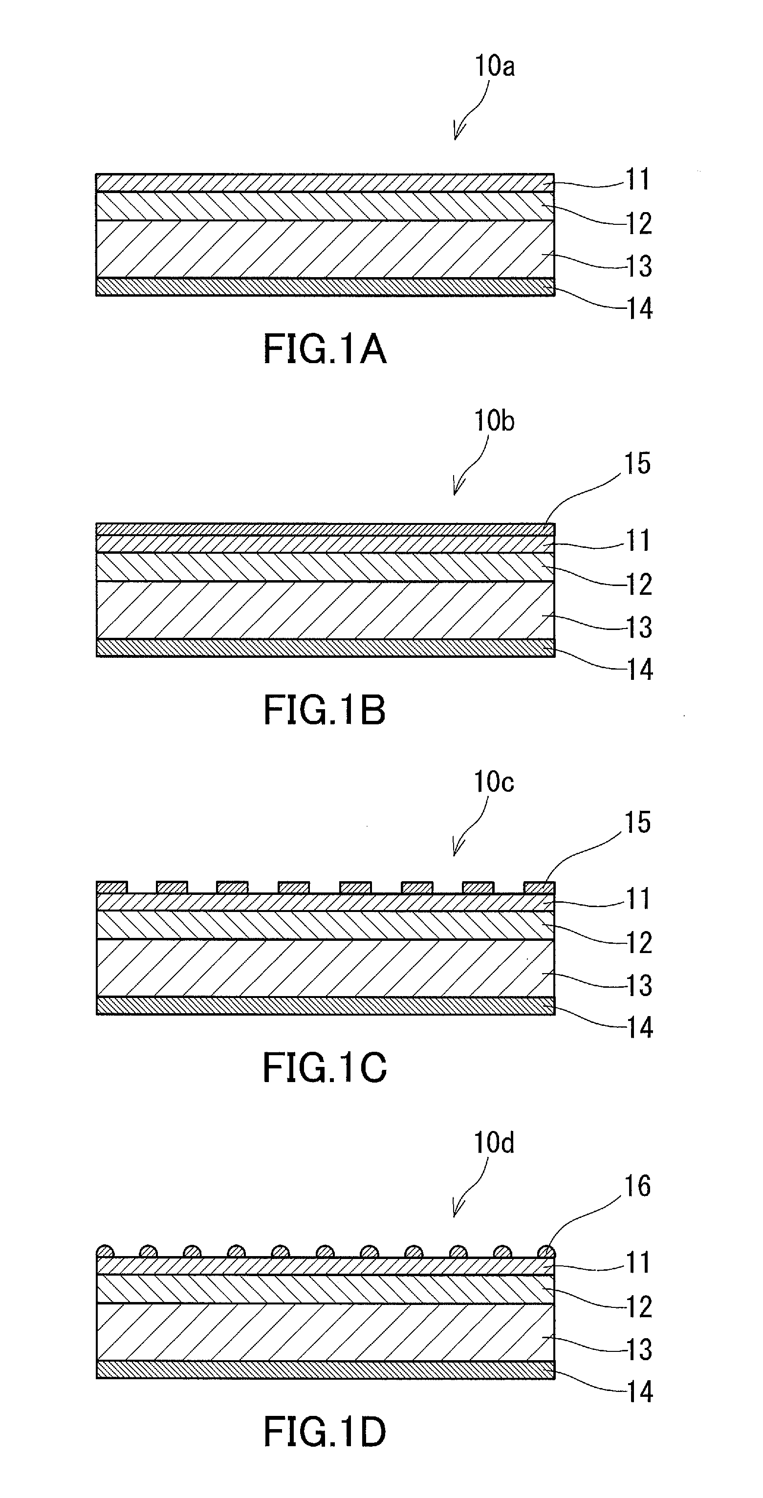
[0131]In Example 1, a multilayer body of an electrode layer, an electrically conductive substrate, a GaN layer, and a Mg-containing AlxGa1-xN layer was used as an anode electrode. On the AlxGa1-xN layer of this multilayer body (on the surface of the AlxGa1-xN layer opposite to the surface thereof facing the GaN layer), fine particles of Ni-containing metal oxide were dispersedly arranged, as shown in FIG. 1D. The electrically conductive substrate was a single-crystal GaN substrate doped with high-concentration Si (with a thickness of about 0.4 mm). The GaN layer was a Si-doped n*-type GaN layer (with a thickness of 3.0 μm and a Si doping concentration of 4.0×10¹⁸ in terms of the number of atoms per cm3). The thickness of the AlxGa1-xN layer was 100 nm, the value of x was 0.10, and the Mg doping concentration was 1.0×10¹⁷ in terms of the number of atoms per cm3. The metal oxide fine particles were fine particles of nickel oxide (with a diameter of several tens of nanometers to severa...

example 2

[0156]A CO2 reduction device was fabricated in the same manner as in Example 1, except that fine particles of nickel oxide were not arranged on the AlxGa1-xN layer of the anode electrode, and the device thus fabricated was irradiated with light in the same manner as in Example 1.

[0157]In Example 2, as in the case of Example 1, it was confirmed that upon irradiation of the AlxGa1-xN layer of the anode electrode with light, a gas was evolved from the surface of the AlxGa1-xN layer of the anode electrode and that carbon monoxide and formic acid were produced by the reduction of CO2 contained in the first electrolyte solution in the cathode chamber.

[0158]Next, the value of current flowing between the electrodes during light irradiation in Example 2 was compared with that in Example 1. The value of current in Example 2 was almost equal to that in Example 1. The amount of CO2 reduction products (carbon monoxide and formic acid) produced in a given period of irradiation time in Example 2 w...

example 3

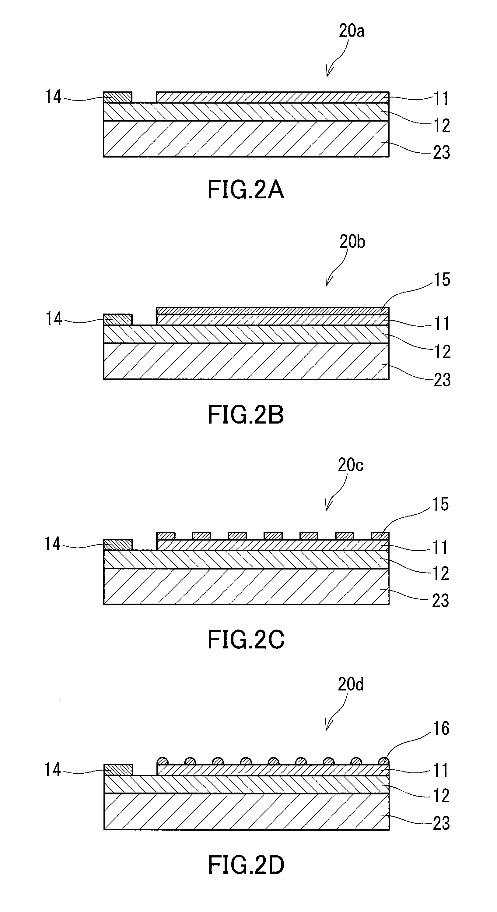
[0159]In Example 3, a CO2 reduction device was fabricated in the same manner as in Example 1, except that an insulating substrate (single-crystal sapphire substrate with a thickness of about 0.4 mm) was used instead of an electrically conductive substrate as the substrate of the anode electrode and that the electrode layer was placed on the GaN layer (see FIG. 2D) instead of on the surface of the substrate opposite to the surface thereof facing the GaN layer. The electrode layer was placed in such a manner that the Ti film was in contact with the GaN layer to increase the adhesion between the electrode layer and the GaN layer and to reduce the interfacial resistance therebetween.

[0160]The AlxGa1-xN layer of the anode electrode in the CO2 reduction device thus fabricated was irradiated with light in the same manner as in Example 1. As a result, it was confirmed that a gas was evolved from the surface of the AlxGa1-xN layer of the anode electrode and that carbon monoxide and formic ac...


PUM

PropertyMeasurementUnit
wavelengthaaaaaaaaaa
band gapaaaaaaaaaa
thicknessaaaaaaaaaa

Abstract

A device for reducing CO2 by light, including: a cathode chamber holding a first electrolyte solution that contains CO2; an anode chamber holding a second electrolyte solution; a proton conducting membrane disposed in a connecting portion between these chambers; a cathode electrode; and an anode electrode. The cathode electrode has a CO2 reduction reaction region composed of a metal or a metal compound, and the anode electrode has a photochemical reaction region composed of nitride semiconductors. The photochemical reaction region of the anode electrode has a multilayer structure of a GaN layer and an AlxGa1-xN layer containing Mg (0<x≦0.25). The content of Mg in the AlxGa1-xN layer is 1×10¹⁵ or more and 1×10¹⁹ or less in terms of the number of Mg atom per cm3. The anode electrode is disposed in such a manner that the AlxGa1-xN layer can be exposed to light.

Description

[0001]This is a continuation of International Application No. PCT / JP2014 / 002526, with an international filing date of May 13, 2014, which claims the foreign priority of Japanese Patent Application No. 2013-100944, filed on May 13, 2013, the entire contents of both of which are hereby incorporated by reference.BACKGROUND OF THE INVENTION[0002]1. Field of the Invention[0003]The present disclosure relates to a carbon dioxide reduction device for reducing carbon dioxide by light energy and to a method for reducing carbon dioxide using this device.[0004]2. Description of Related Art[0005]Carbon dioxide (CO2) is a substance that plays an important role in reserving carbon atoms in the global carbon cycle. Given that CO2 is a reservoir of carbon atoms, it is also a substance that can serve as a carbon source for various carbon compounds as typified by organic compounds. However, since CO2 is an energetically very stable substance, the use of CO2 as a carbon source requires a high level of ...

Claims


Application Information

Patent Timeline
Patent Type & Authority Applications(United States)
IPC IPC(8): C25B15/00C25B1/00C25B3/04C01B32/50C25B3/25
CPCB01J27/24C25B11/04C25B3/04C25B9/00B01J23/52C25B15/00B01J23/745B01J23/75B01J35/004C25B1/003B01J23/72C25B3/25C25B1/55C25B9/19C25B11/091
Inventor DEGUCHI, MASAHIROYOTSUHASHI, SATOSHIHASHIBA, HIROSHIYAMADA, YUKAOHKAWA, KAZUHIRO
Owner PANASONIC CORP
Why Eureka
Try Eureka