Method of feedback commanding a monophase resonant converter, a related monophase resonant converter and a polyphase resonant converter

Active Publication Date: 2015-08-06
STMICROELECTRONICS SRL
View PDF17 Cites 34 Cited by
  • Summary
  • Abstract
  • Description
  • Claims
  • Application Information

AI Technical Summary

Benefits of technology

[0020]It would be desirable to carry out a voltage conversion directly from the bus at 48V down to the supply voltage of microprocessors (or of a generic low voltage load) ensuring the stability of the feedback loop in all functioning conditions and keeping constant the modulation gain when the re

Problems solved by technology

1) Latency of the response to load variations due to the fixed working frequency;
2) Voltage dynamics at the secondary inductors that depend upon the compensation operated by the error amplifier EA;
3) Optimization of the system efficiency only at a certain duty cycle;
4) Difficulty of compensation because of the complex control law;
5) It does not allow to work in sink mode.
The second drawback is very dangerous because it may compromise reliability of the converter.
In

Method used


Image

  • Method of feedback commanding a monophase resonant converter, a related monophase resonant converter and a polyphase resonant converter
  • Method of feedback commanding a monophase resonant converter, a related monophase resonant converter and a polyphase resonant converter
  • Method of feedback commanding a monophase resonant converter, a related monophase resonant converter and a polyphase resonant converter

Examples


Embodiment Construction

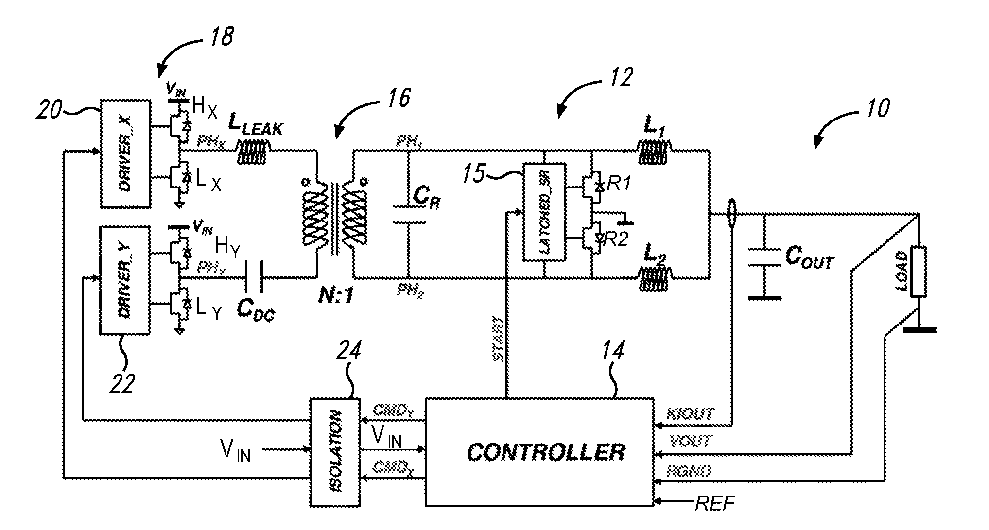
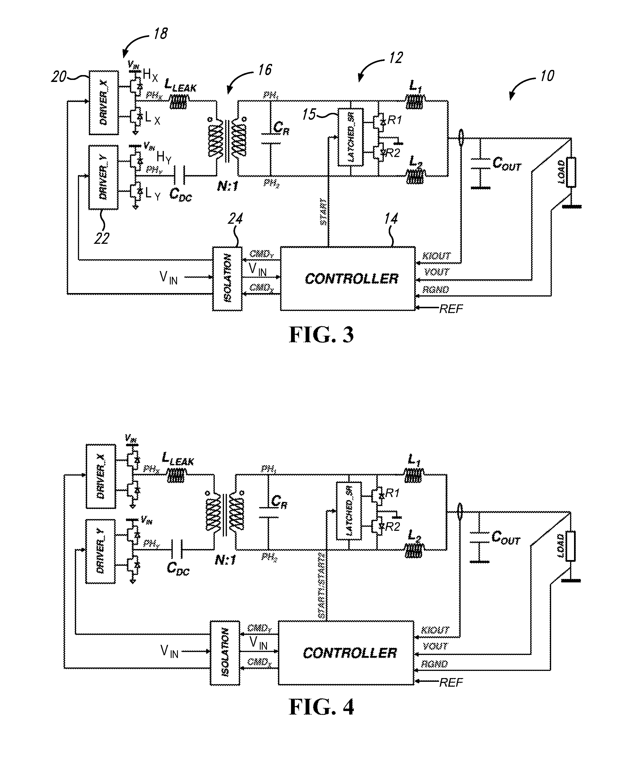
[0056]Alternative embodiments of resonant converters according to this disclosure are shown in FIGS. 3 to 5. It has a full-bridge topology with resonance capacitor at the secondary (CR).

[0057]The blocking capacitor CDC is optional; its function is to block the DC component at the primary side in order to allow to circulate only AC current. The herein proposed converter 10 has a rectification stage 12 capable of receiving signals from a controller 14, that enables the rectification stage. Once the logic circuitry 15 of the rectification stage 12 receives the signal START, the MOSFET R1 (R2) will be “released” (turned off) if and only if the voltage PH1 (PH2) at the secondary side is positive (current entering in the MOSFET) is closed as soon as the voltage PH1 (PH2) attains OV. From this instant onwards, the MOSFET R1 (R2) will be kept on up to the next pulse START even if the current throughout the MOSFET R1 (R2) is entering in it. In other words, the MOSFET R1 (R2) is “released” (t...


PUM


Abstract

A resonant converter includes a primary switching circuit having a primary winding and a primary switching stage configured to drive the primary winding; a secondary resonant circuit having a secondary winding magnetically coupled to the primary winding, a resonance capacitor connected in parallel to the secondary winding, and first and second secondary inductors respectively coupled between an output terminal of the converter and respective terminals of the resonance capacitor; a rectification stage connected in parallel with the resonance capacitor, and having first and second switches coupled to form a half-bridge; and a feedback command circuit. The command circuit is configured to receive feedback signals representing an output voltage and an output current at the output terminal of the resonant converter, receive voltages at the terminals of the resonance capacitor, and turn on/off, independently with respect to each other, the switches of the rectification stage and the primary switching stage.

Description

BACKGROUND[0001]1. Technical Field[0002]This disclosure relates to resonant converters and more particularly to a method of feedback commanding a monophase resonant converter, to a related monophase resonant converter and to a polyphase resonant converter.[0003]2. Description of the Related Art[0004]Power distribution in server and data-center fields is continuously expanding. For continuous improvement of these electronic devices it is desirable to maximize the efficiency of voltage converters that supply them in order to minimize the supplied power for providing the same used power, in order to limit thermal dissipation in environments in which they are installed and thus the power absorbed by the relative cooling appliances.[0005]There are various voltage distribution systems, powered by the mains voltage, to generate the VCPU supply voltage for processors. Presently, the mains voltage is converted into a first voltage distributed through a main supply bus, then converted into a ...

Claims


Application Information

Patent Timeline
IPC IPC(8): H02M3/335H02M1/00
CPCH02M3/33546H02M2001/0058H02M3/3376H02M3/33592H02M1/0058H02M3/1586Y02B70/10H02M1/0009H02M1/08
Inventor ZAMBETTI, OSVALDO ENRICOSAGGINI, STEFANO
Owner STMICROELECTRONICS SRL
Why Eureka
Try Eureka