Stimulated emission depletion microscopy

Active Publication Date: 2015-08-13
ISIS INNOVATION LTD
View PDF1 Cites 43 Cited by
  • Summary
  • Abstract
  • Description
  • Claims
  • Application Information

AI Technical Summary

Benefits of technology

[0028]adapting the pattern on the depletion light modulator to r

Problems solved by technology

Both system- and sample-induced aberrations of the depletion laser beam can dramatically decrease the beam quality and create non-negligible minimum intensities.
On the downside, however, the helicoidal phase mask creates a toroidal depletion-focus, that results in a highly anisotropic effective PSF that is confined in the lateral (xy) plane but still diffraction-limited in the axial (z) direction.
Unfortunately, this approach is far more susceptible to aberrations than the helicoidal phase mask approach and, not surprisingly, no 3D STED imaging has been demonstrated to date in thick samples.
One approach to avoiding aberrations is to embed the sample, for example tissue, in a refractive index-matching med

Method used


Image

  • Stimulated emission depletion microscopy
  • Stimulated emission depletion microscopy
  • Stimulated emission depletion microscopy

Examples


Embodiment Construction

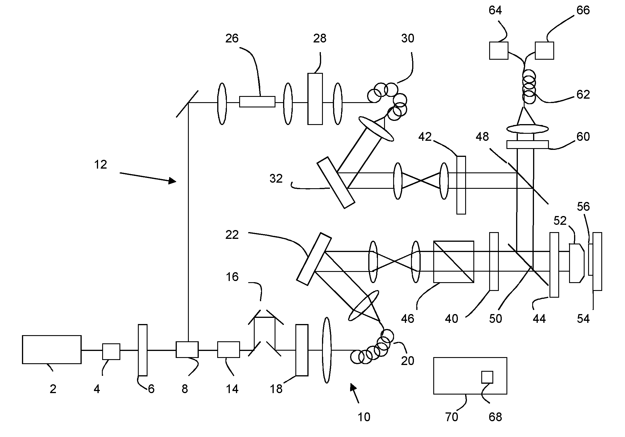
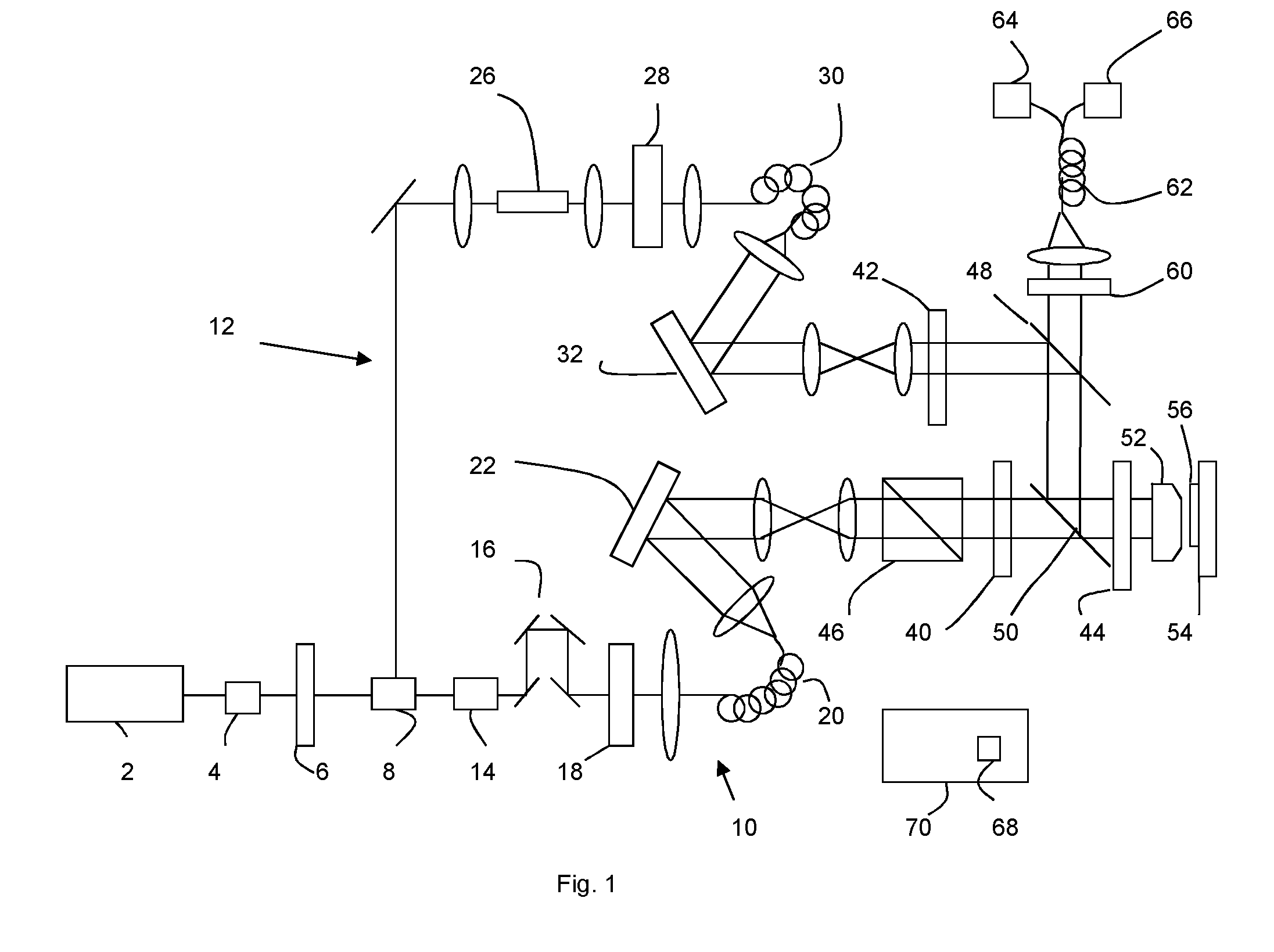
[0039]FIG. 1 illustrates the AO STED setup used in an example embodiment. The output from an 80 MHz mode-locked Ti:Sapphire laser 2 was passed through a Faraday isolator 4 and a half-wave plate 6 before being split into two beam paths 10,12 by a Glan laser polarizer 8. The transmitted beam 10 was used for STED illumination, i.e. for depletion, and hence the corresponding optical path will be referred to as the depletion pulse beam path 10. This beam was passed through a 19 cm long glass block 14, a delay stage 16 for pulse delay adjustment, and an acousto-optical modulator 18 for laser power adjustment before it was coupled into a 100 m long polarization-maintaining single mode fiber 20. The glass block and single mode fiber served to stretch the pulses to a few hundred picoseconds.

[0040]To generate synchronized excitation pulses, the excitation beam along excitation beam path 12 reflected at the Glan laser polarizer was focused into a photonic crystal fiber 26 (SCG-800, Newport—®)....


PUM


Abstract

Aberrations in stimulated emission depletion microscopy are corrected using an adaptive optics approach using a metric which combines both image sharpness and brightness. Light modulators (22,32) are used to perform aberration correction in one or more of the depletion path (10), the excitation path (12), or the emission path from sample to detector.

Description

FIELD OF INVENTION[0001]The invention relates to a method of stimulated emission depletion microscopy, computer program code for such a method and a stimulated emission depletion microscope.RELATED ART[0002]Stimulated emission depletion (STED) microscopy is used to image both thin samples such as single cells but also thick samples such as tissue sections, nematodes or even living mice. The technique is a fluorescence microscopy technique.[0003]STED microscopy overcomes the diffraction limit by superimposing a conventional excitation focus with a second laser focus of high intensity—the depletion-focus—which is red-shifted with regard to the peak of the fluorescence spectrum and features a central intensity minimum (ideally an intensity zero). The depletion laser forces excited fluorophores back to the ground state by stimulated emission and thereby suppresses fluorescence at the periphery of the excitation focus, leaving only fluorescence in a very small central intensity minimum t...

Claims


Application Information

Patent Timeline
IPC IPC(8): G02B21/00G01N21/63G01N21/64
CPCG02B21/0072G01N21/636G02B21/0076G01N21/6458G02B26/06G01N21/6456
Inventor BOOTH, MARTINBURKE, DANIELBEWERSDORF, JOERGGOULD, TRAVIS J.
Owner ISIS INNOVATION LTD
Why Eureka
Try Eureka