Metal nanoparticle complex and method for producing same

a technology of metal nanoparticles and complexes, which is applied in the direction of organic compounds/hydrides/coordination complexes, physical/chemical process catalysts, cell components, etc., can solve the problems of reduced precipitation amount of ruthenium metal in the vicinity of the center of the mof, increased size of ruthenium metal precipitated in the vicinity of the surface, and limited effect of the composite of metal nanoparticles and pcp, etc., to achieve high activity ratio ratio ratio

Inactive Publication Date: 2015-08-20
KYOTO UNIV
View PDF3 Cites 15 Cited by
  • Summary
  • Abstract
  • Description
  • Claims
  • Application Information

AI Technical Summary

Benefits of technology

[0015]The composite of the present invention allows metal nanoparticles each having high activity to be uniformly dispersed in a porous organic structure. Therefore, the composite of the present invention has high activity as a catalyst such as a catalyst for organic synthesis or an electrode catalyst and is extremely useful.
[0016]Further, the ratio between the organic structure and the metal nanoparticles can be adjusted with a heating time and a heating temperature. That is, the physical properties of the composite can be easily controlled by changing the ratio between the organic structure derived from the polyvalent ligand of a complex and the metal nanoparticles.
[0017]In one preferred embodiment, in the case where the composite of the present invention is heated to decompose the organic substance, the reduction in weight is 70 wt % or less. That is, the ratio of the metal nanoparticles is very large in the composite of the present invention. As a result, the characteristics of the metal nanoparticles can be exhibited sufficiently.
[0018]As related-art methods of introducing metal nanoparticles into a complex such as a PCP, there are given a procedure involving synthesizing metal nanoparticles and forming a composite of the metal nanoparticles with the complex such as the PCP and a procedure involving synthesizing the complex such as the PCP and synthesizing the metal nanoparticles. In both of the procedures, reactions are required to be performed in a number of stages. Further, it is difficult to obtain a composite in which the metal nanoparticles are singly-dispersed in the complex such as the PCP.
[0019]The present invention enabled, for the first time, a composite to be manufactured easily, the composite including metal nanoparticles dispersed in an organic structure derived from a PCP, the metal nanoparticles and the organic structure derived from the PCP or the like being in direct contact with each other without using a protecting agent.

Problems solved by technology

Therefore, the composite has a structure in which the metal nanoparticles each adhere to an outside of the PCP or the vicinity of a surface thereof, and thus an effect of the composite of the metal nanoparticles and the PCP is limited.
However, this method has a problem in that ruthenium is liable to be precipitated on a surface of the MOF, and hence a size of the ruthenium metal precipitated in the vicinity of the surface increases whereas a precipitated amount of the ruthenium metal in the vicinity of the center of the MOF decreases.

Method used


Image

  • Metal nanoparticle complex and method for producing same
  • Metal nanoparticle complex and method for producing same
  • Metal nanoparticle complex and method for producing same

Examples


production example 1

Preparation of PCP Complex

[0076]2,000 ml of DMF-ethanol-water (1:1:1 by volume) serving as a solvent, Ni (NO3)2.6H2O (23.8 g), and 2,5-dihydroxyterephthalic acid (H4dhtp, 4.8 g) were added to a 3,000-ml recovery flask, and a reaction was conducted with stirring at 100° C. for 5 days. A precipitated three-dimensional structure metal complex (Ni2(dhtp)) was recovered by suction filtration and washed with methanol and water. Then, the resultant was dried under reduced pressure at 25° C. for 24 hours to obtain 12 g of an intended metal complex (Ni2 (dhtp)). It was confirmed by powder X-ray structure analysis that the intended metal complex was obtained. The obtained metal complex is sometimes hereinafter referred to as “Ni-MOF-74”.

production example 2

Preparation of PCP Complex

[0077]200 ml of DMF-ethanol-water (1:1:1 by volume) serving as a solvent, Co (NO3)2.6H2O (2.4 g), and 2,5-dihydroxyterephthalic acid (H4dhtp, 0.5 g) were added to a 300-ml recovery flask, and a reaction was conducted with stirring at 100° C. for 5 days. A precipitated three-dimensional structure metal complex (Co2(dhtp)) was recovered by suction filtration and washed with methanol and water. Then, the resultant was dried under reduced pressure at 25° C. for 24 hours to obtain 0.8 g of an intended metal complex (Co2(dhtp)). It was confirmed by powder X-ray structure analysis that the intended metal complex was obtained.

example 1

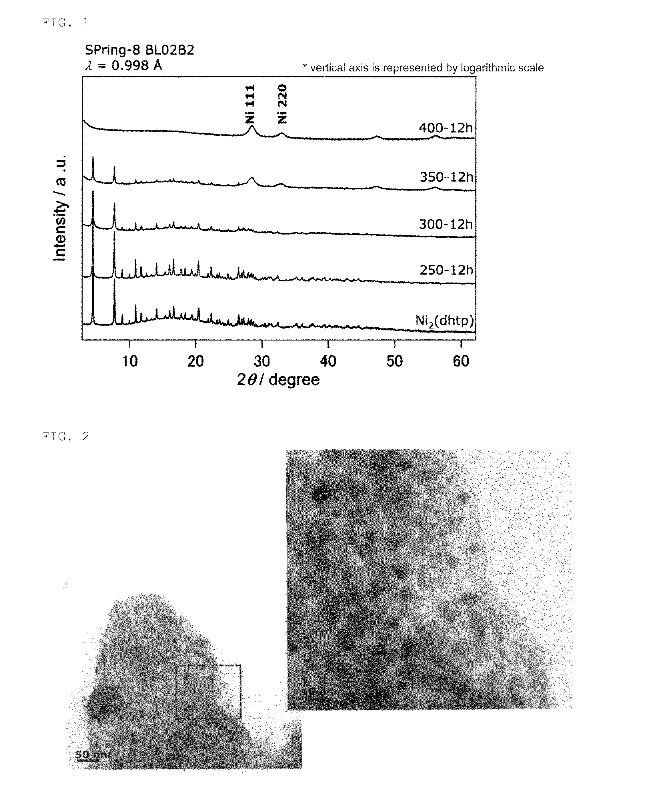
[0078]The Ni complex obtained in Production Example 1 was heated under reduced pressure (under vacuum) through use of a vacuum pump at each reaction temperature and each reaction time of Table 2 below to manufacture a Ni composite of the present invention.

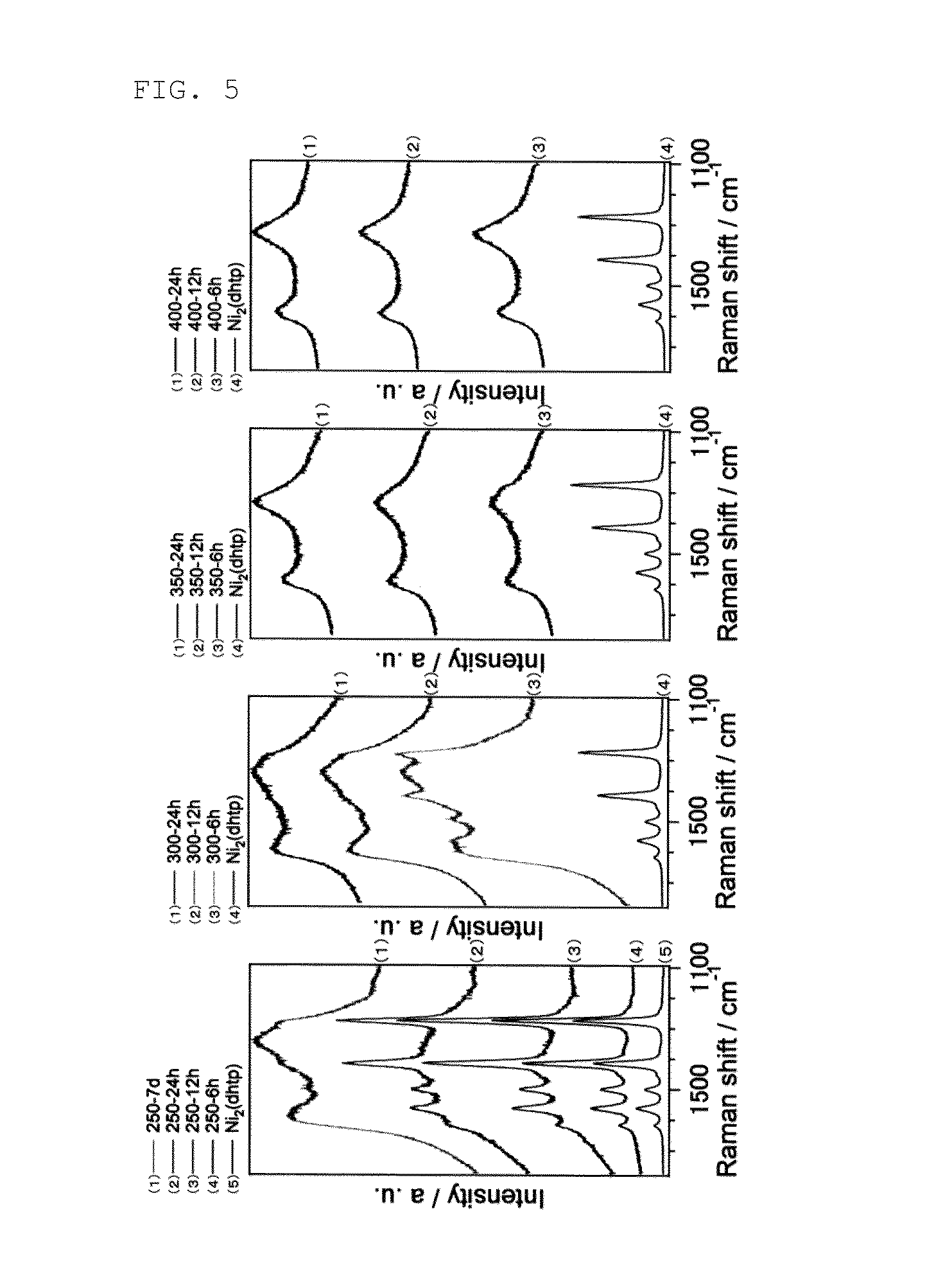
TABLE 2Synthesis condition and batch name6 hours12 hours24 hours3 days7 days250° C.250-6 h250-12 h250-24 h250-7 d300° C.300-6 h300-12 h300-24 h300-3 d350° C.350-6 h350-12 h350-24 h400° C.400-6 h400-12 h400-24 h

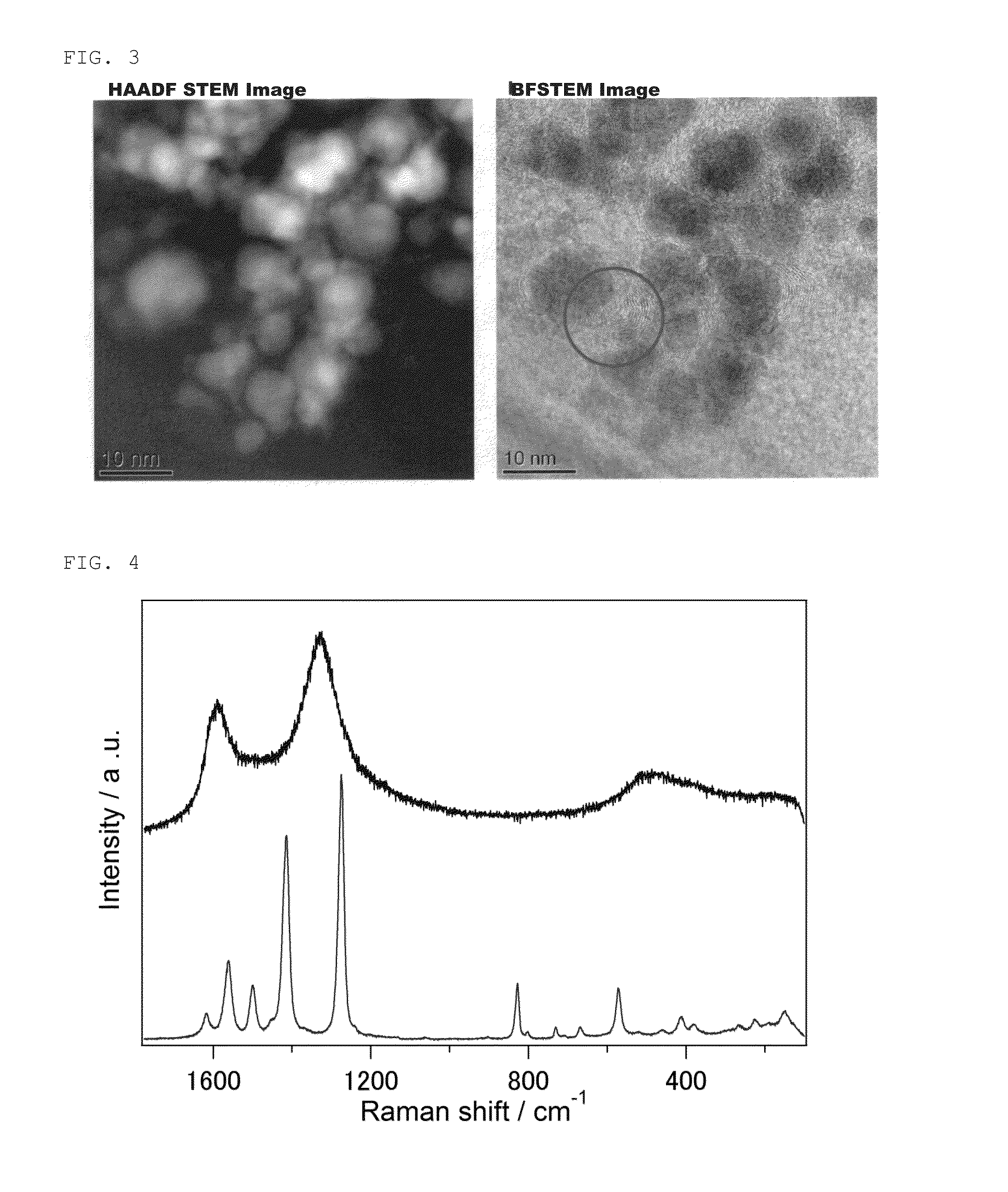
[0079]FIG. 1 shows results of powder X-ray diffraction of the obtained Ni composite. FIG. 2 shows scanning transmission electron microscope (STEM) images of the obtained Ni composite. FIG. 3 shows high-resolution transmission electron microscope (HRTEM) images of the obtained Ni composite. FIGS. 4 and 5 show Raman measurement results of the obtained Ni composite. FIG. 6 shows results of N2 adsorption at 77 K of the obtained Ni composite.


PUM

PropertyMeasurementUnit
temperatureaaaaaaaaaa

Abstract

The present invention provides a metal nanoparticle composite having a structure, in which metal nanoparticles are dispersed in an organic structure, the organic structure including: a structure of a porous coordination polymer (PCP) or metal-organic framework (MOF) containing a metal and a polyvalent ligand capable of reducing the metal; and carbon.

Description

TECHNICAL FIELD[0001]The present invention relates to a metal nanoparticle composite and a manufacturing method for the metal nanoparticle composite.[0002]Note that herein a MOF and a PCP are sometimes collectively referred to as “PCP”.BACKGROUND ART[0003]Hitherto, a large number of PCP / metal nanoparticle composites have been developed. In order to efficiently realize reactions peculiar to the composites, it is necessary to develop a composite in which metal nanoparticles are located in a PCP so as to be in direct contact therewith. Further, from the viewpoint of a manufacturing cost of the composite, there is a demand for a method of manufacturing a PCP / metal nanoparticle composite easily and reliably.[0004]In order to manufacture the PCP / metal nanoparticle composites, there has been used a procedure involving synthesizing metal nanoparticles and covering the circumference of the metal nanoparticles with a PCP or a procedure involving synthesizing metal nanoparticles in (or outside...

Claims


Application Information

Patent Timeline
Patent Type & Authority Applications(United States)
IPC IPC(8): B01J31/22B01J23/755B01J23/75B22F1/054
CPCB01J31/2208B01J23/75B01J23/755B01J2540/12B01J2531/845B01J2531/847B01J2231/70B22F9/24B82Y30/00B82Y40/00B01J21/18B01J35/0013B01J35/002B01J35/0033B01J37/0209H01M8/1013H01M4/9083B01J37/086B01J31/1691B01J31/2239B01J2231/62B01J2231/763Y02E60/50B22F1/054
Inventor KITAGAWA, HIROSHIYAMADA, TEPPEIKOBAYASHI, HIROKAZUMUKOYOSHI, MEGUMI
Owner KYOTO UNIV
Why Eureka
Try Eureka