Carbon-based fluorescent tracers as oil reservoir nano-agents

a technology of fluorescent nanoagents and oil reservoirs, which is applied in the direction of survey, transportation and packaging, borehole/well accessories, etc., can solve the problems of interpreting seismic volumes, narrow view, and giving a wide view

Active Publication Date: 2015-08-20
CORNELL UNIVERSITY +1
View PDF4 Cites 18 Cited by
  • Summary
  • Abstract
  • Description
  • Claims
  • Application Information

AI Technical Summary

Problems solved by technology

One overriding problem in exploring for hydrocarbons in the subsurface is related to the probing and characterization of an environment that cannot be seen.
In the first instance, the data is handicapped by the insufficiency of the resulting data, by virtue of being sourced from a single 6-inch hole, thus giving a very narrow of a view of the reservoir as a whole.
Interpreted seismic volumes, on the other hand, typically give too broad of a view due to their imaging quality and resolution inadequacies.
Even combining the two data types, does not enable for the mapping of exact high permeability pathways.
The final uncertainty of integrated models, however, can only be marginally better than the average uncertainty inherent in each the various methods used.
Additionally, as oil fields mature, it is expected that fluid injection for pressure support (i.e., secondary enhanced oil recovery) will increasingly tend to erratically invade and irregularly sweep the residual oil leg.
Concerns have led to needs to identify, detect and map pathways that may lead injected fluids prematurely updip along encroachment fingers.
More often than not, the encroachment materializes faster than even the worst case expectations, and commonly in quite unpredictable directions.
Moreover, premature encroachment is commonly tortuous and will change direction in 3D volume.
This type of tortuosity renders high permeability pathway prediction nearly impossible to satisfactorily pin down.
In spite of an arsenal of cutting-edge technologies that can be thrown at such problems, high permeability pathway prediction capability continues to suffer from high levels of uncertainty.
Even with current technology, it is impossible to work out and predict an exact pathway that fluid fingering will take as it invades deep into an oil leg, much less where it will go next.
The resultant maps provide an indirect, unreliable and a crude way of trying to depict the geology of a reservoir.
Moreover, the map resolutions are too broad to even remotely represent most geological features that would commonly be associated with high permeability pathways.
Other interwell methods to map permeability pathways are, likewise, handicapped by resolution problems.
Borehole detection methods are the most exact, but are also plagued with major shortcomings, such as for mapping purposes, wellsite data must be extrapolated and transformed into interwell information.
Extrapolation in itself creates many problems.
Some disadvantages associated with molecular (chemical) tracers include diffusivity and adsorption.
Molecular tracers, due to their small size, tend to diffuse into all of the small pores of a matrix (as compared with larger tracers), and thus take longer periods of time to travel between the injection well and the production well.
Geostatistical distribution of attributes, including fractures detected on borehole image logs, at the wellbore, is only statistical, and natural geological landscapes are too variable to respond comfortably to the smooth, clean logic of mathematics.
The capabilities become limitless with the possibility of having functionalized molecular agents that “illuminate” the reservoir and possibly intervene to rectify adverse transport conditions in the medium.
As worldwide petroleum reserves decrease and their recovery becomes increasingly difficult, methods for locating and mapping petroleum reservoirs becomes more and more critical.

Method used


Image

  • Carbon-based fluorescent tracers as oil reservoir nano-agents
  • Carbon-based fluorescent tracers as oil reservoir nano-agents
  • Carbon-based fluorescent tracers as oil reservoir nano-agents

Examples


example 1

Synthesis of A-Dots (Carbon-Dots)

[0059]In a typical process, 4.2 g citric acid monohydrate and 3.66 g ethanolamine were dissolved separately in 10 mL of deionized water and mixed using a magnetic stirrer. The reaction mixture was then heated to about 70° C. on a hot plate under constant stifling to evaporate the majority of the water from the reaction mixture. When the reaction mixture became syrupy, the magnetic bar was removed and the reaction mixture was placed in a furnace and heated of at least about 200° C. in air at a rate of 10° C. / min for at least about 3 hrs. The resulting black product was allowed to cool to room temperature and used without any further purification. The products are highly soluble / dispersible in water.

[0060]In certain embodiments, the synthesis of the A-Dots leads to uniformly sized hybrid nanoparticles (hairy) that are readily dispersible in water and organic solvents, depending upon the length and type of ligands that are attached to the carbon core.

[0...

example 2

Scale Up Synthesis of A-Dots (Carbon-Dots)

[0062]For the scale up synthesis of A-Dots, 378 g of citric acid monohydrate and 330 g of ethanolamine were separately added to two large beakers and combined with enough deionized water was added to each to bring the volume to 900 mL. After complete dissolution, the ethanolamine solution was added to the citric acid solution under constant magnetic stifling. The mixture was stirred and heated at 70° C. on a hot plate to evaporate most of the water. After the volume was reduced to about 650 mL, the mixture was transferred to 1 L glass bottles and heated at 200° C. in air at a rate of 10° C. / min for 8 hrs.

example 3

Characterization of A-Dots

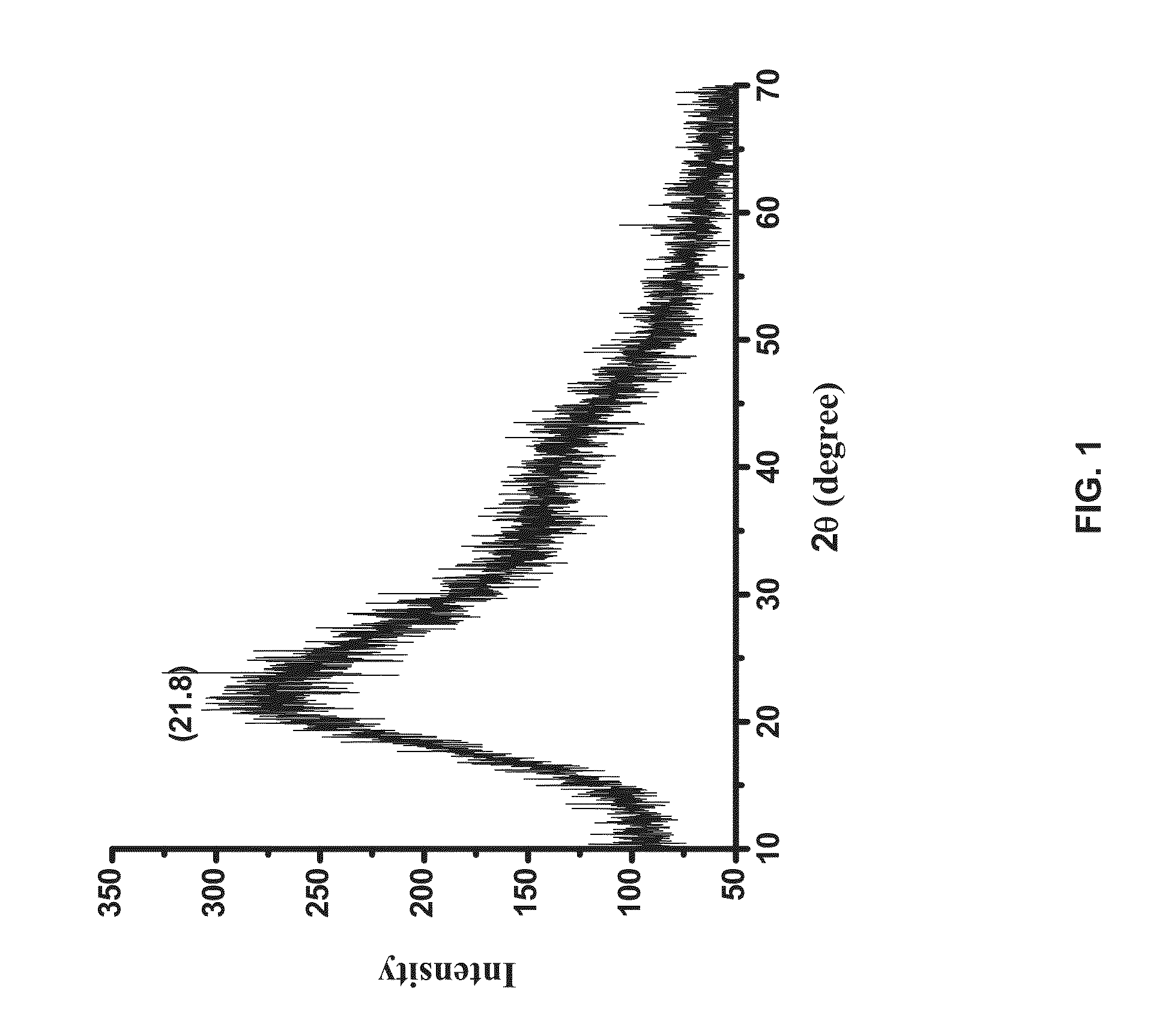
[0063]The carbon-dots were synthesized via a one-pot reaction using the citrate salt as a precursor. When citric acid and ethanolamine are mixed, the corresponding ammonium carboxylate salt is formed. During pyrolysis, the citrate part of this precursor molecule provides the source of carbon for the core with the remaining ammonium groups attached to the surface. The reaction leads to uniform size hybrid (hairy) nanoparticles in high yield that are readily dispersible in water or organic solvents, depending on the type and length of ammonium hairs attached to the carbon core. Referring to FIG. 5, TEM images of the carbon-dots prepared from an aqueous solution show uniform particles having an average diameter of less than about 10 nm. Referring now to FIG. 6, the resulting nanoparticles are negatively charged having a zeta potential of about −26 mV. Without wishing to be bound by any single theory, the negative charge and zeta potential are possibly due to t...


PUM

PropertyMeasurementUnit
temperatureaaaaaaaaaa
emission at a wavelengthaaaaaaaaaa
widthaaaaaaaaaa

Abstract

The present invention relates to carbon-based fluorescent nano-agent tracers for analysis of oil reservoirs. The carbon-based fluorescent nano-agents may be used in the analysis of the porosity of a formation. The nanoagents are suitable for injection into a petroleum reservoir and may be recovered from the reservoir for the determination of hydrocarbon flow rates and retention times.

Description

RELATED APPLICATIONS[0001]This application is a divisional of U.S. patent application Ser. No. 13 / 469,459, filed on May 11, 2012, which claims priority to U.S. Provisional Patent Application No. 61 / 486,090, filed on May 13, 2011, the disclosures both of which are incorporated herein by reference in their entireties.FIELD OF THE INVENTION[0002]The present invention relates to carbon-based fluorescent nano-agent tracers for analysis of oil reservoirs, and methods of making and using same.BACKGROUND OF THE INVENTION[0003]Crude oil is the world's main source of hydrocarbons that are used as fuel and petrochemical feedstock. One overriding problem in exploring for hydrocarbons in the subsurface is related to the probing and characterization of an environment that cannot be seen. Similarly, after a hydrocarbon deposit has been discovered and is ready to be developed and exploited, many assumptions must be made by reservoir geologists and reservoir engineers in the modeling of a large volu...

Claims


Application Information

Patent Timeline
Patent Type & Authority Applications(United States)
IPC IPC(8): C09K11/06C07H15/04E21B49/00C09K11/65
CPCC09K11/06C09K11/65C07H15/04B82Y20/00C09K2211/10Y10S977/774Y10S977/95E21B49/00C09K9/02C09K2208/10C01B32/15Y10T428/2982Y10S977/773Y10S977/896E21B47/11C07C227/18C07C235/74E21B49/008C07C215/08C07C231/02B82Y40/00
Inventor KANJ, MAZEN Y.RASHID, MOHAMMAD HARUNARGIANNELIS, EMMANUEL
Owner CORNELL UNIVERSITY
Why Eureka
Try Eureka