Vehicle drive device

a technology of vehicle drive and drive shaft, which is applied in the direction of machines/engines, reciprocating combination engines, etc., can solve the problems of difficult difficulty in difficulty in oil cooling of electric motors, so as to improve thermal performance, improve cooling performance of second electric motors, and improve electric motor cooling performance

Active Publication Date: 2015-08-27
TOYOTA JIDOSHA KK
View PDF5 Cites 19 Cited by
  • Summary
  • Abstract
  • Description
  • Claims
  • Application Information

AI Technical Summary

Benefits of technology

[0009]Consequently, even in a configuration with the prime mover and the electric motor coupled to the input-side rotating member of the hydraulic power transmission device, the prime mover and the electric motor are arranged at the positions with the hydraulic power transmission device interposed therebetween in the axial direction, the electric motor can be housed in the oil chamber. Since the electric motor is housed in the oil chamber, the electric motor can be oil-cooled and, therefore, the cooling performance of the electric motor can be improved.
[0010]Preferably, the second aspect of the invention provides the vehicle drive device recited in the first aspect of the invention further comprising a second electric motor coupled to the output-side rotating member of the hydraulic power transmission device, wherein the second electric motor is disposed between the electric motor and the transmission in the axial direction in the oil chamber. Consequently, since the second electric motor is housed in the oil chamber housing the transmission as is the case with the electric motor, the second electric motor can also be oil-cooled and the cooling performance of the second electric motor can also be improved.
[0011]Preferably, the third aspect of the invention provides the vehicle drive device recited in the second aspect of the invention, wherein an oil pressure generating device is disposed between the electric motor and the second electric motor in the axial direction in the oil chamber, and wherein a drive gear of the oil pressure generating device is coupled to the input-side rotating member of the hydraulic power transmission device via a first shaft disposed in parallel with an axis on an inner circumferential side of the electric motor. Consequently, when the input-side rotating member of hydraulic power transmission device rotates, the drive gear is rotated and the oil pressure generating device is operated. Since the oil pressure generating device is disposed between the electric motor and the second electric motor, heat transfer between the electric motor and the second electric motor is suppressed and thermal performance is improved.
[0012]Preferably, the fourth aspect of the invention provides the vehicle drive device recited in the third aspect of the invention, wherein a second shaft parallel to the axis is disposed on an inner circumferential side of the first shaft, wherein the hydraulic power transmission device is a torque converter, wherein a stator impeller of the torque converter is coupled via a one-way clutch and the second shaft to a cover member that is a non-rotating member of the oil pressure generating device, and wherein the second shaft and the cover member are coupled. Consequently, an oil passage for supplying operating oil to the hydraulic power transmission device can be formed between the inner circumferential surface of the first shaft and the outer circumferential surface of the second shaft. Since the oil passage is made up of the members different from the rotation shaft of the electric motor, the heat transfer between the oil passage and the electric motor is suppressed.
[0013]Preferably, the fifth aspect of the invention provides the vehicle drive device recited in the third or fourth aspect of the invention, wherein terminal blocks of the electric motor and the second electric motor are disposed on an outer circumferential side of the oil pressure generating device. Consequently, since a space is formed on the outer circumferential side of the oil pressure generating device, the terminal blocks of the electric motor and the second electric motor can be disposed in the space with shifted phases so as to effectively utilize the space.
[0014]Preferably, the sixth aspect of the invention provides the vehicle drive device recited in the first aspect of the invention, wherein a partition wall is formed between the hydraulic power transmission device and the electric motor with a seal member disposed on an inner circumferential portion of the partition wall, and wherein the seal member seals the oil chamber. Consequently, the intrusion of foreign material into the oil chamber is prevented. This seal member can also be used as the seal between the hydraulic power transmission device and the transmission and an increase in the number of parts can be suppressed. Since the air chamber and the oil chamber can be partitioned by the partition wall, heat transfer between the hydraulic power transmission device and the electric motor is suppressed.

Problems solved by technology

This configuration makes oil cooling of the electric motor difficult and cooling performance of the electric motor may be insufficient.
Therefore, the oil cooling of the electric motor is difficult also in Patent Document 2 and the cooling performance of the electric motor may be insufficient.

Method used


Image

  • Vehicle drive device
  • Vehicle drive device
  • Vehicle drive device

Examples


example

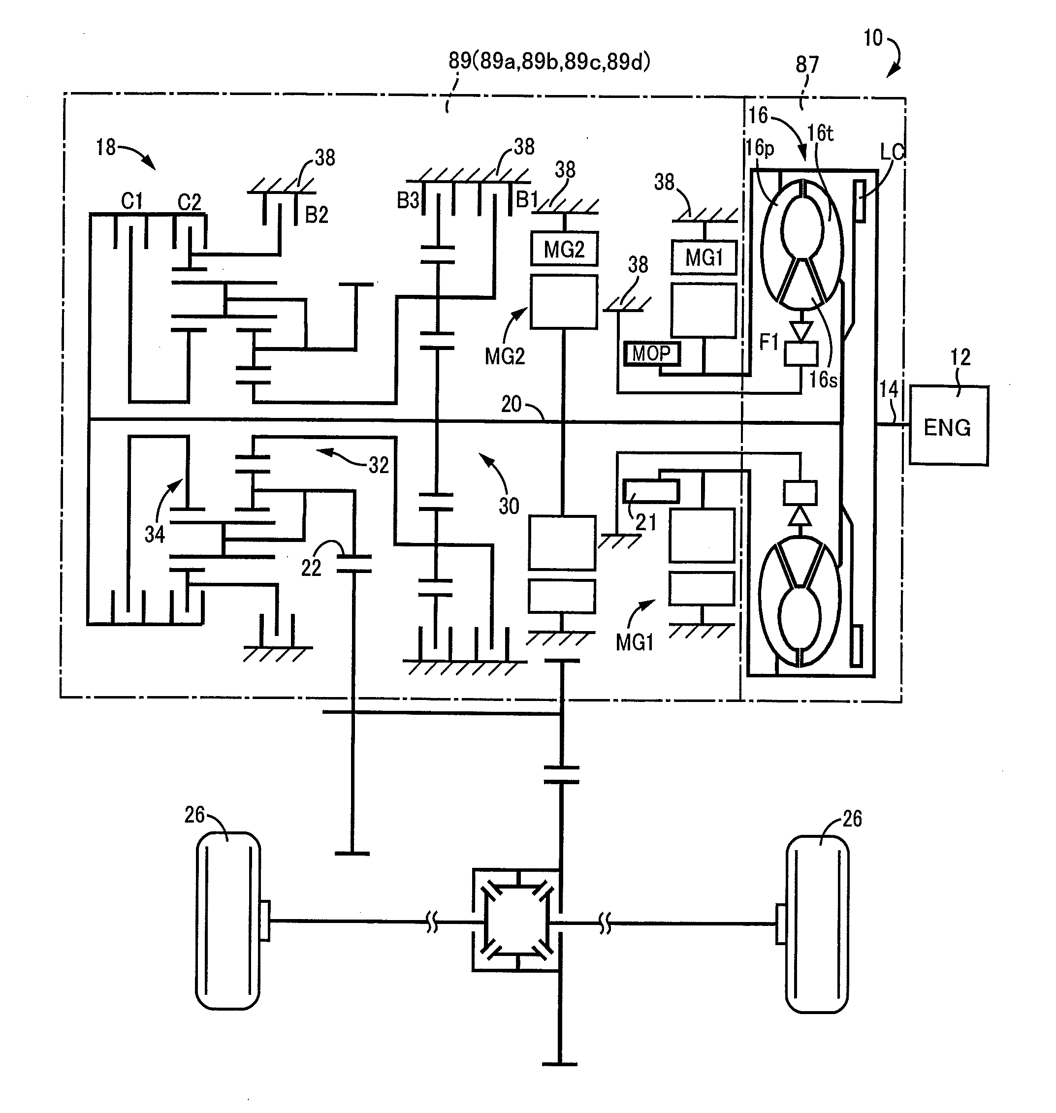
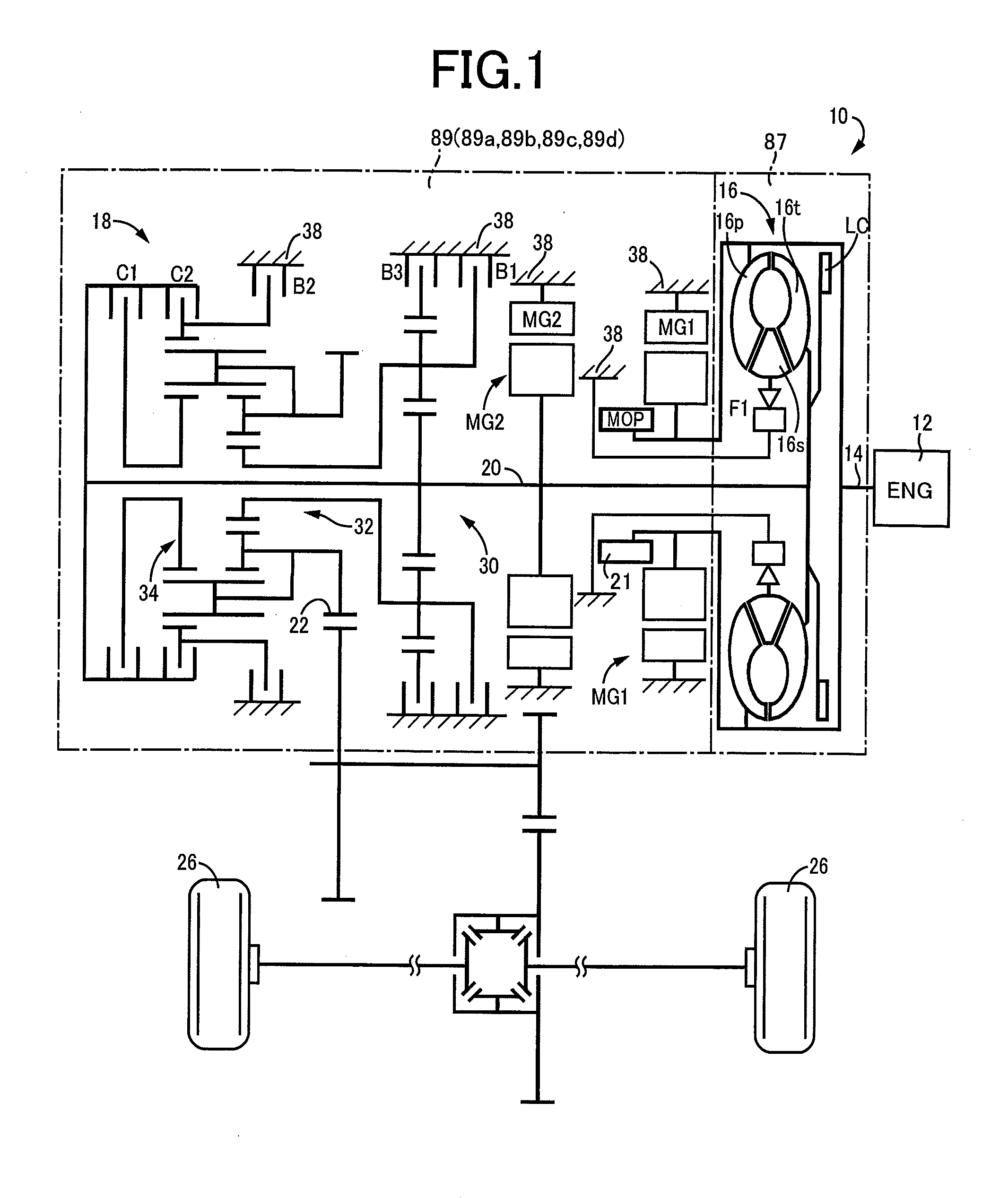
[0023]FIG. 1 is a schematic for explaining a configuration of a vehicle drive device 10 that is an example of the present invention. In FIG. 1, the vehicle drive device 10 is preferably employed in FF (front-engine front-drive) type vehicles and includes an engine 12 acting as a prime mover, a torque converter 16 coupled to a crankshaft 14 of the engine 12, an automatic transmission 18 disposed between the torque converter 16 and drive wheels 26 and coupled to an output-side of the torque converter 16 (corresponding to a hydraulic power transmission device of the present invention), a first electric motor MG1 disposed between the torque converter 16 and the automatic transmission 18 and coupled to a pump impeller 16p that is an input-side rotating member of the torque converter 16, and a second electric motor MG2 disposed between the first electric motor MG1 and the automatic transmission 18 and coupled to a turbine impeller 16t that is an output-side rotating member of the torque c...


PUM


Abstract

A vehicle drive device includes: a torque converter having an input-side rotating member to which power from a prime mover is input and an output-side rotating member outputting power to drive wheels; an electric motor coupled to the input-side rotating member; a transmission coupled to the output-side rotating member of the torque converter; and a case member housing the torque converter, the electric motor, and the transmission, the case member having an air chamber and an oil chamber, the prime mover and the electric motor being disposed at positions with the torque converter interposed therebetween in an axial direction, the torque converter being housed in the air chamber, the electric motor being housed in the oil chamber the vehicle drive device further comprising a second electric motor coupled to the output-side rotating member of the torque converter, the second electric motor being disposed between the electric motor and the transmission in the axial direction in the oil chamber, an oil pressure generating device being disposed between the electric motor and the second electric motor in the axial direction in the oil chamber, and a drive gear of the oil pressure generating device being coupled to the input-side rotating member of the torque converter via a first shaft disposed in parallel with an axis on an inner circumferential side of the electric motor, a second shaft parallel to the axis being disposed on an inner circumferential side of the first shaft, a stator impeller of the torque converter being coupled via a one-way clutch and the second shaft to a cover member that is a non-rotating member of the oil pressure generating device, and the second shaft and the cover member being coupled, and an oil passage for supplying an operating oil to the torque converter being made up of a gap formed between an inner circumferential surface of the first shaft and an outer circumferential surface of the second shaft.

Description

TECHNICAL FIELD[0001]The present invention relates to a configuration of a vehicle drive device including a hydraulic power transmission device having an input-side rotating member to which power from a prime mover is input and an output-side rotating member outputting power to drive wheels, an electric motor coupled to the input-side rotating member, and a transmission coupled to the output-side rotating member of the hydraulic power transmission device.BACKGROUND ART[0002]A vehicle drive device is known that includes a hydraulic power transmission device having an input-side rotating member to which power from a prime mover is input and an output-side rotating member outputting power to drive wheels, an electric motor coupled to the input-side rotating member, and a transmission coupled to the output-side rotating member of the hydraulic power transmission device. A hybrid vehicle drive device of Patent Document 1 is an example thereof. The hybrid vehicle drive device of Patent Do...

Claims


Application Information

Patent Timeline
Patent Type & Authority Applications(United States)
IPC IPC(8): B60K6/26B60K6/383B60K6/50B60K6/36B60L50/16
CPCB60K6/26B60K6/36Y10S903/915B60K6/50B60K6/383B60K6/40B60K6/547B60K6/405B60K6/48B60K6/485B60K2001/006B60K2006/4825B60K6/365B60K6/445Y02T10/62F16H41/00F16H41/02F16H45/00F16H45/02
Inventor OKUDA, KOICHITABATA, ATSUSHIIMAMURA, TATSUYAIMAI, KEITAMIZUSHINO, SHO
Owner TOYOTA JIDOSHA KK
Why Eureka
Try Eureka