Method and magnetic resonance apparatus for determining a pulse sequence

a magnetic resonance apparatus and pulse sequence technology, applied in the direction of reradiation, measurement using nmr, instruments, etc., can solve the problems of steep edge steepness, significant vibration in the apparatus, and the effect of reducing the accuracy of the measuremen

Inactive Publication Date: 2015-08-27
SIEMENS HEALTHCARE GMBH
View PDF11 Cites 3 Cited by
  • Summary
  • Abstract
  • Description
  • Claims
  • Application Information

AI Technical Summary

Benefits of technology

[0015]With the inventive method, it is possible to widen the frequency range of the vibrations by applying a random distribution to the separation of n pulse sequence segments between the pre-pulses. It is thus possible to prevent the occurrence of resonance effects and to reduce the exposure of patient and MR scanner to vibration and noise.
[0024]The user can therefore specify a range for the number of consecutive pulse sequence segments between two pre-pulses or a mean value and a permissible deviation. After each saturation pulse, a randomizing algorithm determines the number of repetitions until the next saturation pulse. Therefore, having established a mean value n and a maximal deviation dn, for example, not just the frequencyf=1TR·nbut the frequency rangef=1TR·(n±dn)will be excited by the magnetic fields or eddy currents generated by the pulse sequence. It is thus possible to prevent the occurrence of resonances or the buildup of shaking.
[0030]The distribution of the random numbers can therefore be narrower for a region around the k-space center. The k-space center is therefore saturated either more intensely or very accurately. This means that either do or n is smaller in the k-space center than in the k-space outer region. The particulars of a recorded structure are usually encoded in the k-space center, and therefore it can be beneficial to reduce the time separations, in which e.g. fat saturation pulses are placed, in this region or at least to ensure that the fat saturation pulses are placed at comparatively regular separations, in order to achieve a particularly high imaging quality of the fine structures or a particularly good contrast.

Problems solved by technology

MR sequences generally cause significant vibrations in the apparatus, and these vibrations are associated with loud noises.
The main cause of the noise is the rapid switching of the imaging gradients.
In particular, such a pronounced steepness of the edge contributes to the known noise phenomena during the switching of the gradients.
The rapidly changing magnetic field causes eddy currents in the structural elements of the apparatus, which can result in forces of attraction or repulsion.
This results in a vibration and clanking of large components, since vibrations outweigh noises in this frequency range.
This low-frequency vibration, which can be perceived by the patient as shaking, not only causes noise to develop, but can also result in the affected scanner components working loose or becoming detached.

Method used


Image

  • Method and magnetic resonance apparatus for determining a pulse sequence
  • Method and magnetic resonance apparatus for determining a pulse sequence
  • Method and magnetic resonance apparatus for determining a pulse sequence

Examples


Embodiment Construction

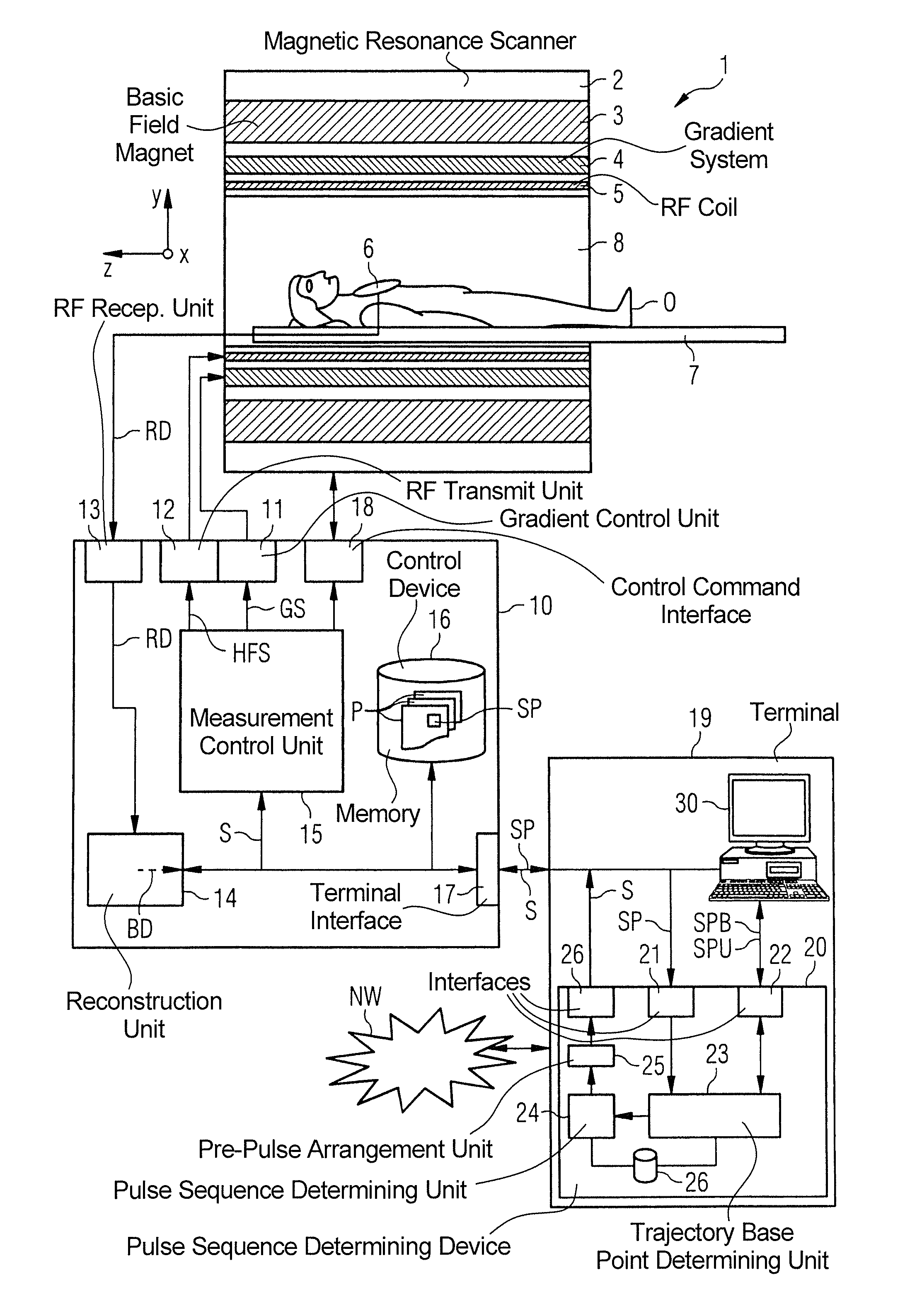
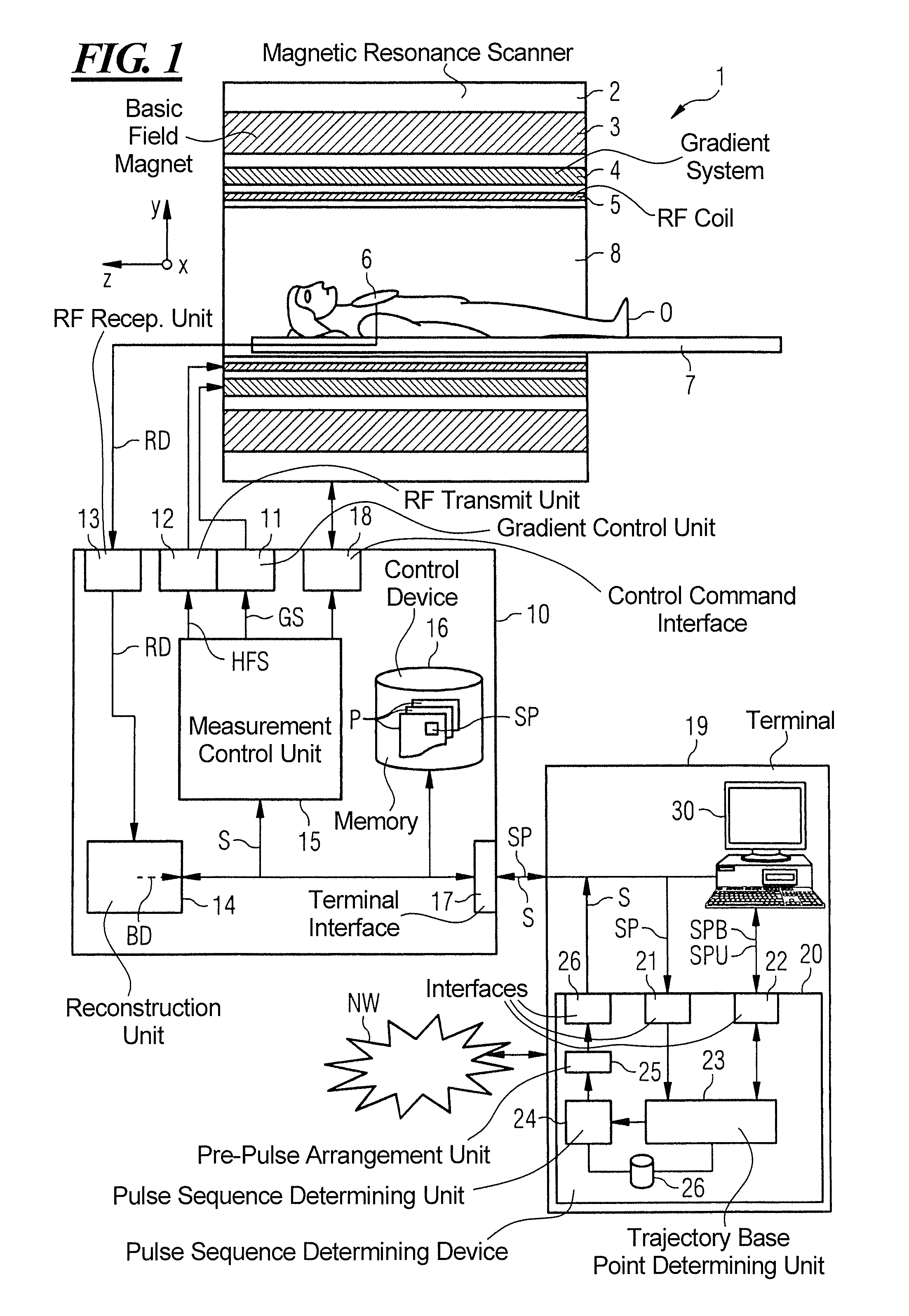
[0036]FIG. 1 provides a basic schematic illustration of a magnetic resonance installation 1 according to the invention. This installation includes the actual magnetic resonance scanner 2 that has an examination volume or patient tunnel 8 therein. A bed 7 can be moved into this patient tunnel 8, such that during an examination a patient O or subject lying thereon can be supported at a specific position within the magnetic resonance scanner 2 relative to the magnetic system and radio-frequency system that is arranged therein, and can also be moved between various positions during a measurement.

[0037]Basic components of the magnetic resonance scanner 2 include a basic field magnet 3, a gradient system 4 with magnetic field gradient coils for generating magnetic field gradients in the x-direction, y-direction and z-direction, and a whole-body radio-frequency coil 5. The magnetic field gradient coils in the x-direction, y-direction and z-direction can be activated independently of each o...


PUM


Abstract

In a method for determining a pulse sequence composed of multiple consecutive pulse sequence segments and multiple pre-pulses, the number of consecutive pulse sequence segments between two pre-pulses is determined on the basis of a randomizing algorithm. A pulse sequence determining device determines a pulse sequence for a magnetic resonance installation, device having an input interface for entering control protocol parameter values, a pulse sequence determining unit for determining the pulse sequence on the basis of the control protocol that has been entered, and a pre-pulse arrangement unit, which establishes the position of the pre-pulses between the pulse sequence segments in a randomly distributed manner.

Description

BACKGROUND OF THE INVENTION[0001]1. Field of the Invention[0002]The invention relates to a method for determining a pulse sequence composed of multiple consecutive pulse sequence segments and a plurality of pre-pulses. The invention further relates to a method for operating a magnetic resonance installation. The invention also relates to a magnetic resonance installation that is designed to operate in accordance with such a method.[0003]2. Description of the Prior Art[0004]Within the MR scanner of a magnetic resonance installation, also known as a magnetic resonance tomography system, the body under examination is usually exposed to a relatively high basic magnetic field of e.g. 1, 3, 5 or 7 Tesla with the use of a basic field magnetic system. In addition, a magnetic field gradient is applied by a gradient system. High-frequency excitation signals (RF signals) are then transmitted via a radio-frequency transmit system by suitable antenna devices, in order to tip (deflect) the nuclea...

Claims


Application Information

Patent Timeline
Patent Type & Authority Applications(United States)
IPC IPC(8): G01R33/54G01R33/48
CPCG01R33/543G01R33/4828G01R33/4818G01R33/5602G01R33/5607
Inventor GRODZKI, DAVID
Owner SIEMENS HEALTHCARE GMBH
Why Eureka
Try Eureka