Eureka AIR delivers breakthrough ideas for toughest innovation challenges, trusted by R&D personnel around the world.

End milling cutter for processing of fiber-reinforced materials such as carobon fiber reinforced plastics (CFRP)

a technology of carobon fiber reinforced plastics and end milling cutters, which is applied in the direction of turning equipment, milling equipment, file, etc., can solve the problems of difficult to say which machining takes, and achieve the effect of improving surface quality and reducing processing tim

Active Publication Date: 2015-09-10
HUFSCHMIED ZERSPANUNGSSYST
View PDF0 Cites 18 Cited by
  • Summary
  • Abstract
  • Description
  • Claims
  • Application Information

AI Technical Summary

Benefits of technology

The present invention aims to improve the surface quality of fiber-reinforced materials by developing an end milling cutter. The cutter combines the features of plastics processing with a plurality of teeth and grooves. It achieves particularly good results in surface quality, even with materials that are reinforced with polyester yarns which are prone to fraying or fanning out. The cutter has a geometry that prevents fiber stumps from protruding from the wall and acts as chip breaker grooves for the cutting edge along the flute. The cutter also has a sharp cutting wedge that can crush or smash large thicknesses of material per revolution. Overall, the cutter improves surface quality faster and more effectively than previous methods.

Problems solved by technology

However, it is difficult to say which machining takes place first or afterwards during the chipping operation of the rotating tool, so that those designations are not intended to be limiting.

Method used


Image

  • End milling cutter for processing of fiber-reinforced materials such as carobon fiber reinforced plastics (CFRP)
  • End milling cutter for processing of fiber-reinforced materials such as carobon fiber reinforced plastics (CFRP)
  • End milling cutter for processing of fiber-reinforced materials such as carobon fiber reinforced plastics (CFRP)

Examples


Embodiment Construction

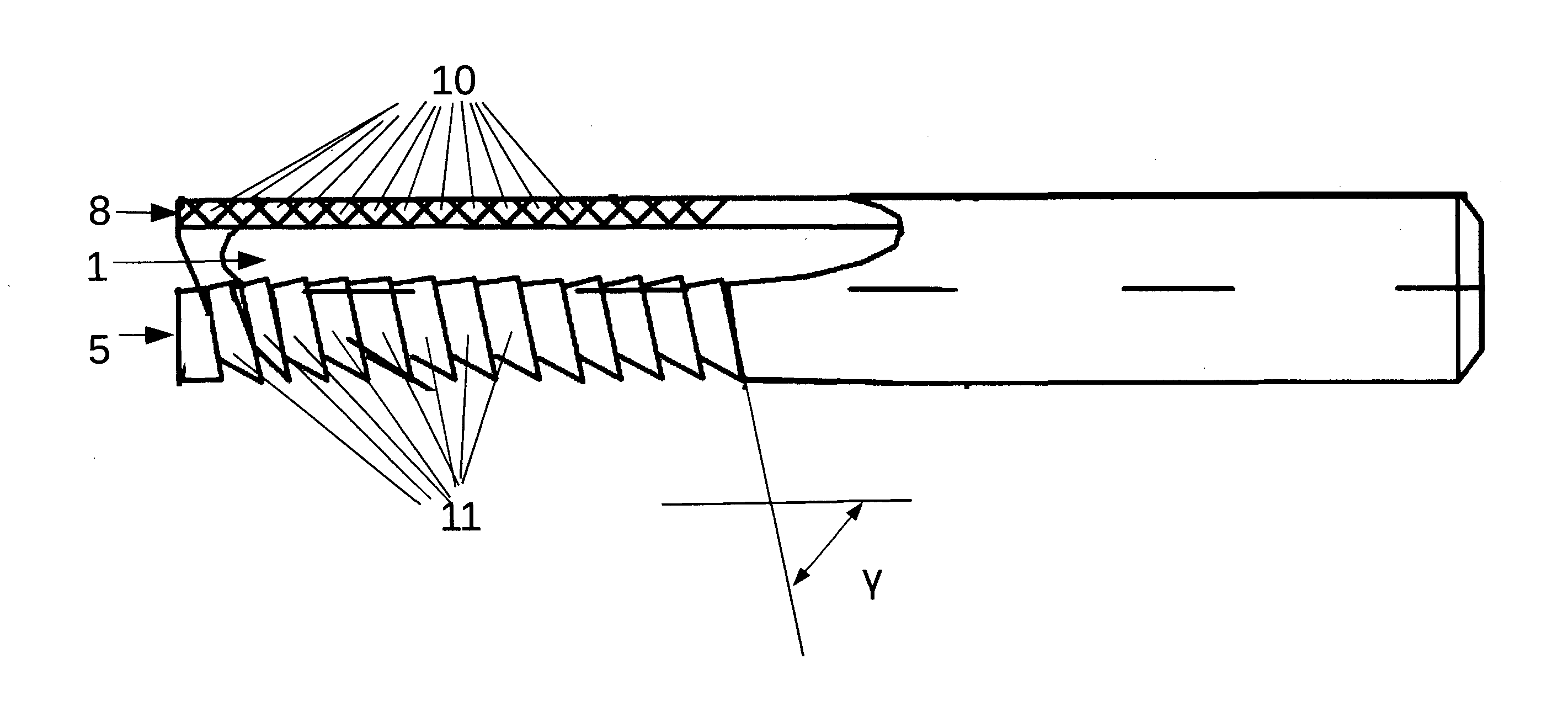
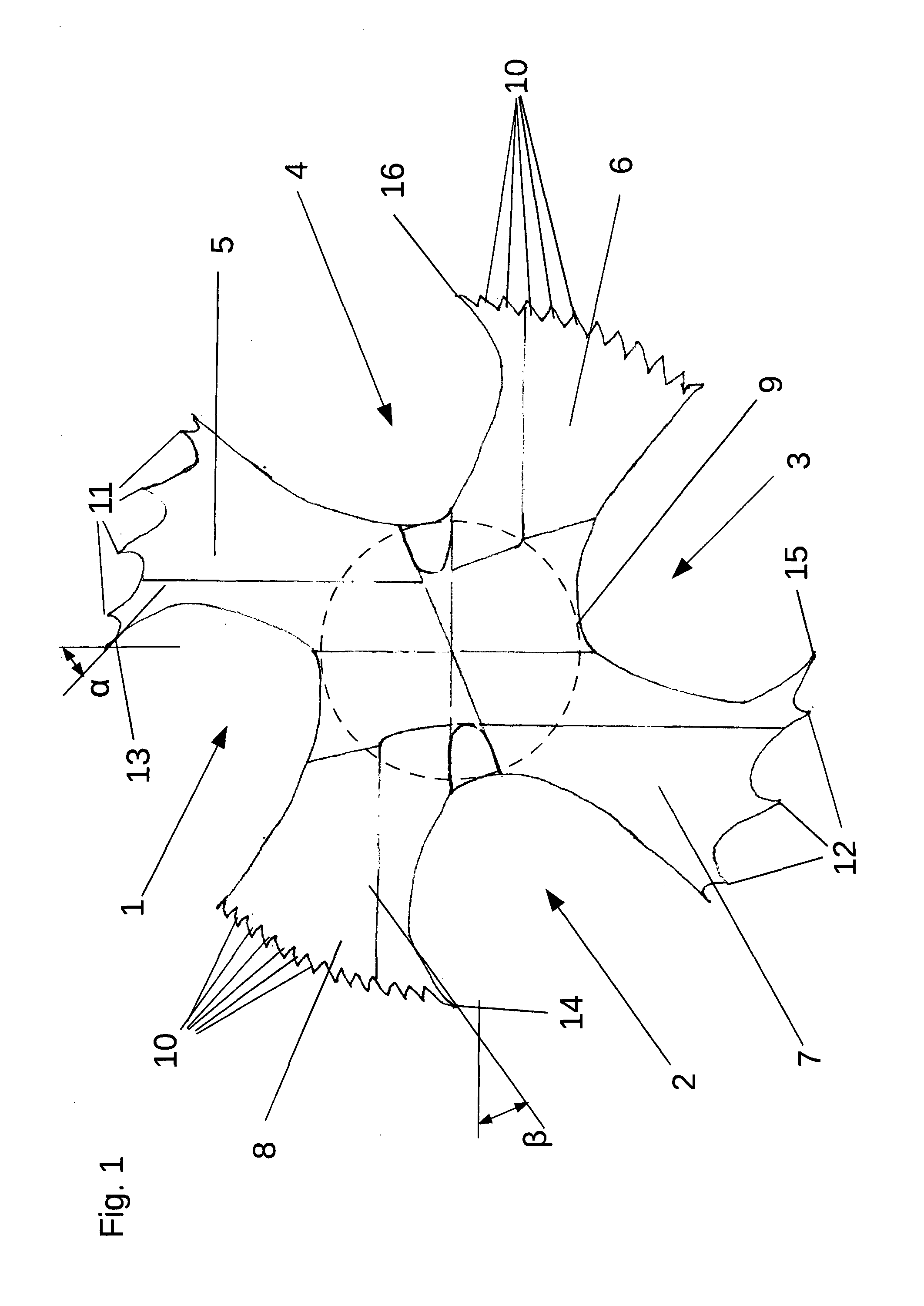
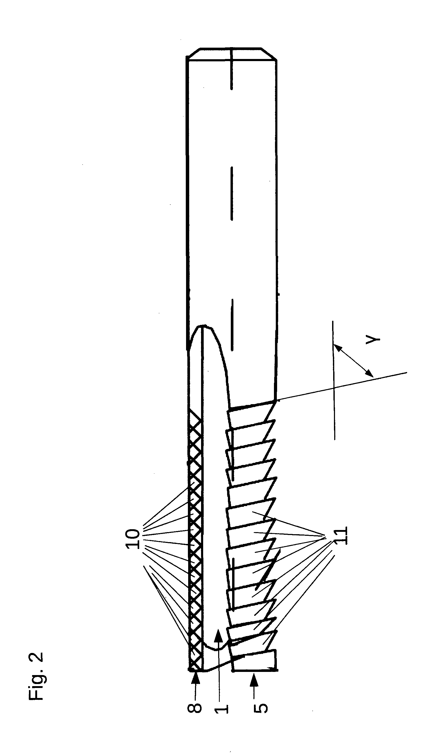
[0031]The end milling cutter shown in the figures has four equidistantly spaced flutes 1, 2, 3, 4, which equidistantly space lands 5, 6, 7, 8 from each other, which are placed around a cylinder core segment 9. At the peripheral outer edge of the lands 5, 6, 7, 8 facing the leading flute 1, 2, 3, 4, a cutting edge 13, 14, 15, 16 is respectively provided on an acute cutting wedge, wherein the rake angles α, drawn in the FIG. 1, on the two lands 5, 7, and 13 on the two lands 6, 8 are of equal size, but are shown somewhat exaggerated in the Figure and in reality be about 8°.

[0032]On the two opposite lands 6, 8, pyramid-shaped teeth 10 are incorporated in their peripheral machining areas extending from the tool tip along the tool axis, by grinding-in of triangular grooves into the circumferential surface of the lands 6, 8 along intersecting lines on the circumferential surface. The two opposite lands 6, 8 thus serve as pre- or rough machining lands that should smash with their teeth 10 d...


PUM


Abstract

The invention concerns a machining tool for machining fiber-reinforced materials such as CFRP, glass-fiber-reinforced plastics or plastics reinforced with polyester threads. The machining tool comprises a plurality of flutes (1, 2, 3, 4) which distance lands (5, 6, 7, 8), disposed about a cylinder core segment (9), from each other in the peripheral sense. At least one of the lands (6, 8) is designed as a premachining land (6, 8) and at least one other of the lands (5, 7) is designed as a postmachining land (5, 7), each comprising a peripheral working region extending along, or with a twist and, in the form of a helical segment about, the tool axis. The working region of each premachining land (6, 8) is designed as a peripheral file with a plurality of teeth (10) which are incorporated in a cylinder surface segment-shaped outer surface of the working region, and provided in the working region of each postmachining land (5, 7) is a number of sharp cutting edges (11, 12, 13, 15) extending parallel to or with a twist and in the form of a helical segment about the tool axis. The invention is characterized in that the number of sharp cutting edges (11, 12, 13, 15) on at least one postmachining land (5, 7) comprises a plurality of cutting edges (11, 12) each provided on a peripheral casing groove, the casing grooves being incorporated in a cylinder surface segment-shaped outer face of the working region, parallel to each other and at a pitch relative to the flute (1, 3) leading at least one postmachining land (5, 7).

Description

CROSS-REFERENCE TO RELATED APPLICATIONS[0001]This application is the U.S. national stage of PCT / EP2013 / 002912 filed Sep. 27, 2013, which claims priority of German Patent Application 10 2012 019 804.3 filed Oct. 10, 2012.TECHNICAL FIELD[0002]The invention relates to an end milling cutter for machining fiber reinforced materials such as CFRP, according to the preamble of claim 1.BACKGROUND DISCUSSION[0003]When milling and drilling of fiber-reinforced materials such as CFRP, GFRP and polyester filament-reinforced plastics, the problem that occurs often is a tearing of individual fibers or polyester yarns are fanning out, when a workpiece of such a material is machined with conventional tools for machining. Thus, individual fibers are torn from the edge of the machined area and others are pressed during passage of the tool to the edge of the machined area, so that they are cut only on an end protruding over the edge of the machined area and therefore protrude over the rim after machinin...

Claims


Application Information

Patent Timeline
Patent Type & Authority Applications(United States)
IPC IPC(8): B23C5/10
CPCB23C5/10B23C2210/321B23C2210/40B23C2220/605B23C2226/27B23C2210/326B23B51/08B23B2226/275Y10T407/1815B23C2210/0485
Inventor HUFSCHMIED, RALF
Owner HUFSCHMIED ZERSPANUNGSSYST
Why Eureka
Eureka Blog
Learn More