

Heat-resistant member and method for manufacturing the same
- Summary
- Abstract
- Description
- Claims
- Application Information
AI Technical Summary
Benefits of technology
Problems solved by technology
Method used
Image

Examples
examples
[0047]Examples of specific production of heat-resistant members will be described below with reference to Experimental Examples. Experimental Examples 1 to 7 correspond to the examples of the present invention and Experimental Examples 8 and 9 correspond to comparative examples.
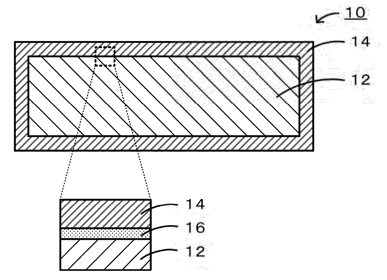
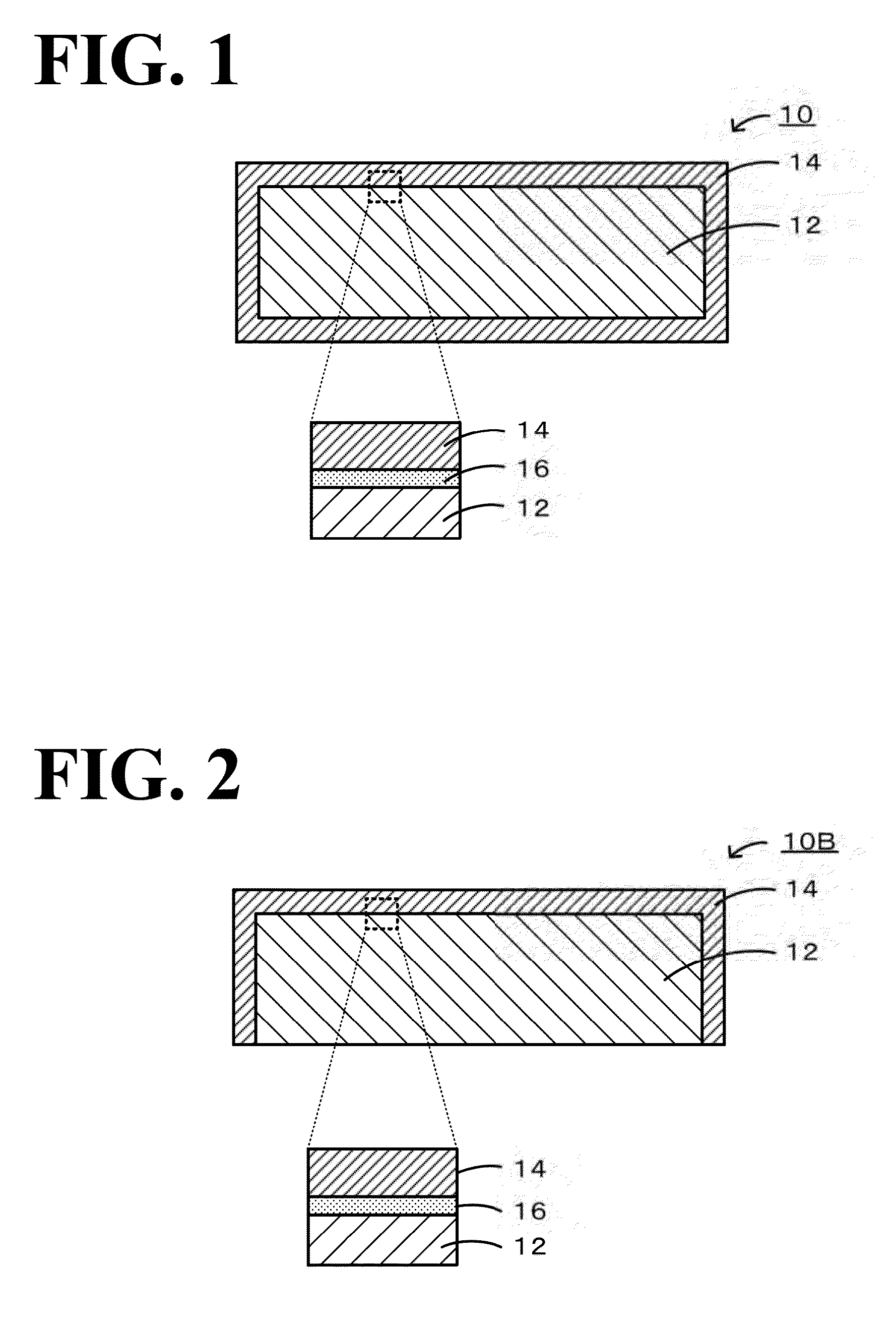
[0048]Production of Heat-Resistant Member
[0049]An Fe—Cr based alloy (stainless steel SUS430) and a Ni based alloy (Inconel 600) serving as metal members were prepared as members to be protected. In addition, a Si-bonded SiC sintered material and a Si-impregnated SiC sintered material serving as ceramic members were prepared as members to be protected. The Si-bonded SiC sintered material was produced as described below. A SiC powder and a metal Si powder were mixed in such a way that the volume ratio became 38:22, and a molding raw material was produced by adding hydroxypropylmethyl cellulose serving as a binder, starch as a pore-forming material, and a water-absorbing resin and, in addition, adding water. The...
experimental examples 1 to 9
[0051]In Experimental Examples 1 and 2, the member which was the object of protection was specified to be an Fe—Cr based alloy, the metal raw material for the protective layer was specified to be an Fe powder, and the second compound (electrically conductive aid) was specified to be TiO2 (1 percent by mole and 3 percent by role, respectively). The Fe powder having an average particle diameter of 3 μm was used. In Experimental Example 3, the member which was the object of protection was specified to be an Fe—Cr based alloy, the metal raw material for the protective layer was specified to be a Cu powder, and an addition material was specified to be Li2CO3 (1 percent by mole). The Cu powder having an average particle diameter of 5 μm was used. In Experimental Examples 4 and 5, the member which was the object of protection was specified to be a Ni based alloy, the metal raw material for the protective layer was specified to be an Fe powder, and the electrically conductive aid was specif...
experimental examples 10 to 14
[0052]In Experimental Examples 10 and 11, the member which was the object of protection was specified to be an Fe—Cr based alloy, the metal raw material for the protective layer was specified to be an Fe powder, and the second compound (electrically conductive aid) was not added. In Experimental Example 10, the firing time was specified to be 5 hour. In Experimental Example 11, the firing time was specified to be 0.5 hour. In Experimental Examples 12 and 13, the member which was the object of protection was specified to be a Si-impregnated SiC sintered material, the metal raw material for the protective layer was specified to be an Fe powder, and the second compound (electrically conductive aid) was specified to be TiO2 (1 percent by mole). In Experimental Example 12, the firing time was specified to be 0.5 hour. In Experimental Example 13, the firing time was specified to be 5 hour. In Experimental Examples 10 to 13, the Fe powder having an average particle diameter of 3 in was use...
PUM
| Property | Measurement | Unit |
|---|---|---|
| Temperature | aaaaa | aaaaa |
| Temperature | aaaaa | aaaaa |
| Thickness | aaaaa | aaaaa |
Abstract
Description
Claims
Application Information