Subnanosecond scintillation detector

a detector and subnanosecond technology, applied in the field of detectors, can solve problems such as the ratio of signal to nois

Active Publication Date: 2015-10-01
CALIFORNIA INST OF TECH
View PDF7 Cites 28 Cited by
  • Summary
  • Abstract
  • Description
  • Claims
  • Application Information

AI Technical Summary

Benefits of technology

[0009]The scintillation detectors further comprise a coating on the surface area, wherein the coating acts as a bandpass filter that transmits light within a range of wavelengths corresponding to the first component of the scintillation and suppresses transmission of light with wavelengths outside said range of wavelengths. The surface area, the passivation layer, and the coating are controlled to increase the temporal resolution of the semiconductor photodetectors.
[0015]The coating can comprise transparent dielectric and reflective metal that forms a Fabry-Perot cavity and / or a photonic bandgap, the coating can suppress the transmission of light outside the range of wavelengths such that the semiconductor photodetector has a quantum efficiency of less than 1% for out-of-band light and the peak quantum efficiency of greater than 50% for the in-band light, and / or the coating can transmit the first component of scintillation with a peak transmission of at least 50%, and the coating suppresses transmission of out-of-band light with a peak transmission of less than 3%.
[0028]In the above PET system, one or more computers can perform a three dimensional calculation of a location of the radionuclide tracer, wherein the first and second scintillations define a line of response and the intersections of the lines of response are used to determine the position of the radionuclide tracer with a first uncertainty, the relative detection times of the first scintillation and the second scintillation are used to determine the position of the radionuclide tracer in an additional dimension with a second uncertainty determined by the temporal resolution of the detector, and the second uncertainty is comparable to the first uncertainty such that the computer has increased ability to reject erroneous lines of response due to background scintillation, the background scintillation including response to pairs of gamma photons that are not emitted by the electron-positron annihilation. In such a PET system, the scan time of the PET can be reduced, and a dosing of the radionuclide tracer can be reduced.

Problems solved by technology

One major challenge facing ultraviolet (UV) detection is visible or solar rejection, as UV photons in bands of interest are often greatly outnumbered by visible photons, effectively reducing the signal to noise ratio.

Method used


Image

  • Subnanosecond scintillation detector
  • Subnanosecond scintillation detector
  • Subnanosecond scintillation detector

Examples


Embodiment Construction

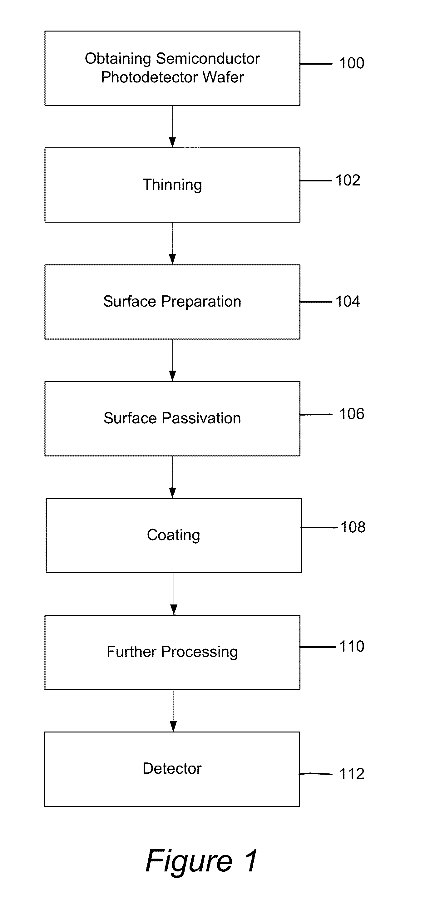
[0055]In the following description of the preferred embodiment, reference is made to the accompanying drawings which form a part hereof, and in which is shown by way of illustration a specific embodiment in which the invention may be practiced. It is to be understood that other embodiments may be utilized and structural changes may be made without departing from the scope of the present invention.

[0056]Technical Description

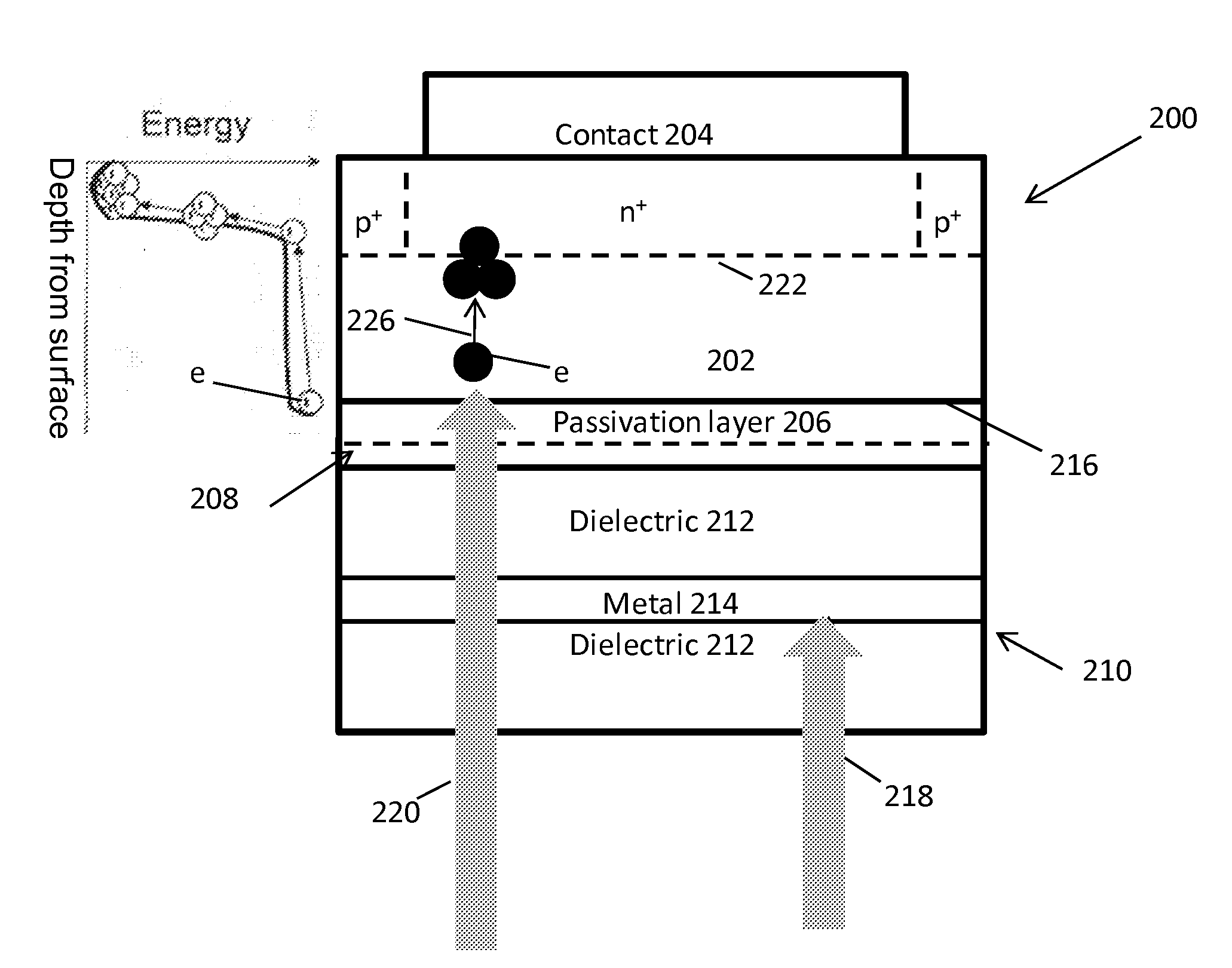
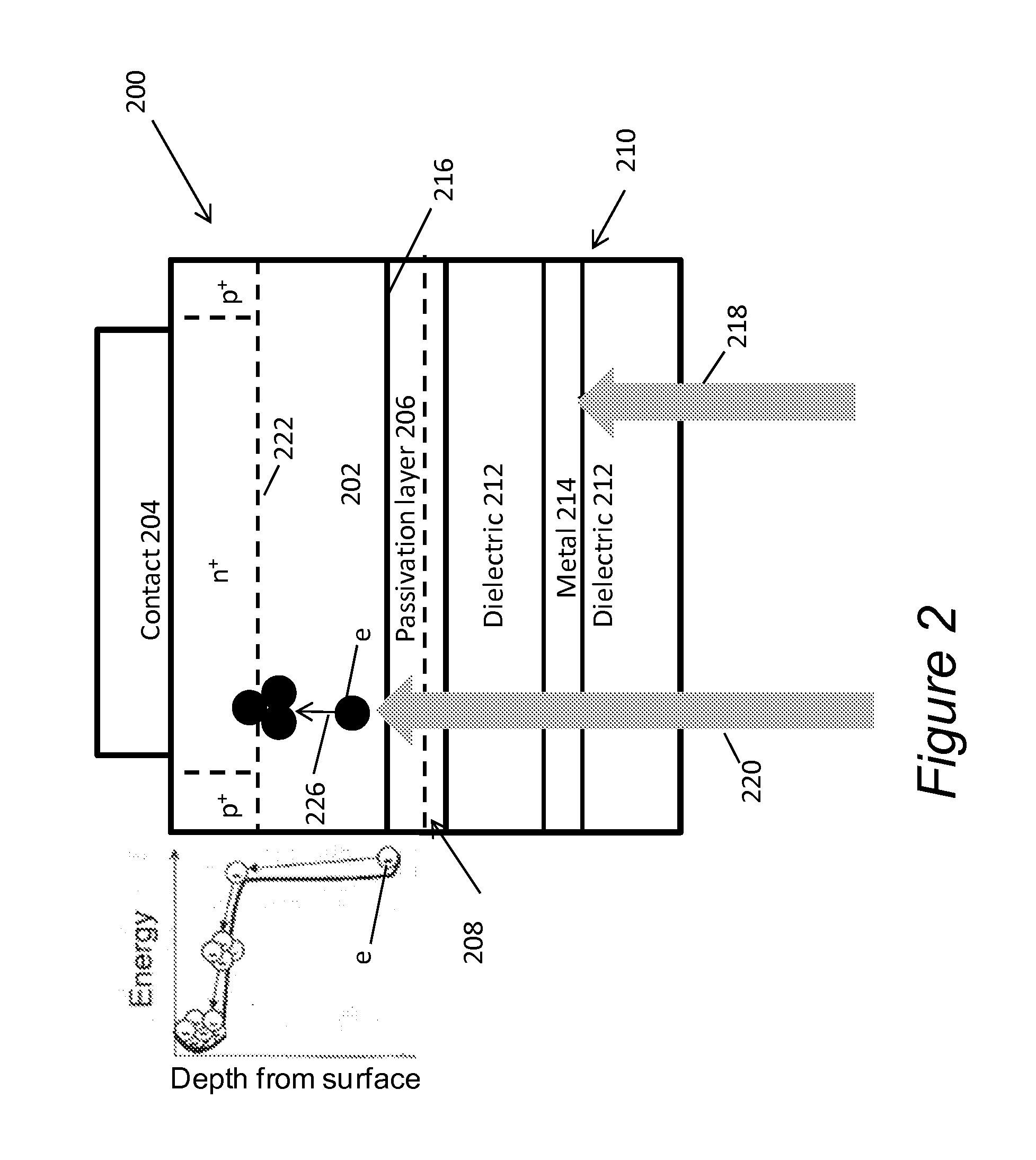
[0057]As noted above, large area solid state detectors with sensitivity around 200 nm and nanosecond rise times have potential applications in astrophysics, high energy physics, and medical imaging. Next generation high energy physics experiments require detectors of high energy gamma rays that can withstand unprecedented rates and radiation doses. Current experiments employ crystals such as PbWO4 or LYSO, which have scintillation decay times of ˜30 ns, which is far too slow for the new high rate experiments being studied. There is a faster crystal, BaF2, with a s...


PUM


Abstract

A scintillation detector, including a scintillator that emits scintillation; a semiconductor photodetector having a surface area for receiving the scintillation, wherein the surface area has a passivation layer configured to provide a peak quantum efficiency greater than 40% for a first component of the scintillation, and the semiconductor photodetector has built in gain through avalanche multiplication; a coating on the surface area, wherein the coating acts as a bandpass filter that transmits light within a range of wavelengths corresponding to the first component of the scintillation and suppresses transmission of light with wavelengths outside said range of wavelengths; and wherein the surface area, the passivation layer, and the coating are controlled to increase the temporal resolution of the semiconductor photodetector.

Description

CROSS REFERENCE TO RELATED APPLICATIONS[0001]This application claims the benefit under 35 U.S.C. Section 119(e) of co-pending and commonly-assigned U.S. Provisional Patent Application Ser. No. 61 / 970,779, filed on Mar. 26, 2014, by Michael Hoenk and David Hitlin, entitled “SUBNANOSECOND SCINTILLATION DETECTOR,” client reference number CIT-6868-P, which application is incorporated by reference herein.STATEMENT REGARDING FEDERALLY SPONSORED RESEARCH AND DEVELOPMENT[0002]The invention described herein was made in the performance of work under a NASA contract, and is subject to the provisions of Public Law 96-517 (35 USC 202) in which the Contractor has elected to retain title.BACKGROUND OF THE INVENTION[0003]1. Field of the Invention[0004]This invention relates to a detector and method of fabricating a detector.[0005]2. Description of the Related Art[0006](Note: This application references a number of different publications as indicated throughout the specification by one or more refer...

Claims


Application Information

Patent Timeline
Patent Type & Authority Applications(United States)
IPC IPC(8): G01T1/24H01L27/146G01T1/20
CPCG01T1/249G01T1/2018H01L27/14663H01L27/14685H01L27/14621G01T1/247G01T1/208G01T1/248
Inventor HOENK, MICHAELHENNESSY, JOHNHITLIN, DAVID
Owner CALIFORNIA INST OF TECH
Why Eureka
Try Eureka