
Cup-type container and method of forming the same

a container and cup-type technology, applied in the field of cup-type containers, can solve the problems of high anisotropy, insufficient heat resistance, and anisotropy in the molecular orientation, and achieve excellent heat resistance, excellent gas-barrier properties, excellent transparency and dimensional precision

Active Publication Date: 2015-10-15
TOYO SEIKAN GRP HLDG LTD
View PDF2 Cites 12 Cited by
  • Summary
  • Abstract
  • Description
  • Claims
  • Application Information

AI Technical Summary

Benefits of technology

The present invention provides a cup-type container with excellent heat resistance and transparency. The container is oriented isotropically, meaning it is symmetrically shaped without any anisotropic arrangement of molecules. The rate of forming in the compression forming method is slowed down to control the flow of resin in the direction of height, resulting in the orientation of resin molecules being suppressed in the direction of height and the P-value being controlled. Even when the container has a multi-layer structure, the rate of forming is controlled to establish a parabolic flow in the space for forming the body portion. This permits the intermediate layer to stretch together with the inner and outer layers, allowing for excellent gas-barrier properties without being impaired. The container is formed from a transparent, dimensionally precise resin using a special method.

Problems solved by technology

However, a thin cup-type container made from a polypropylene by injection forming or pressure forming has a high degree of anisotropy in the molecular orientation of the container, and cannot provide a sufficient degree of heat resistance and is not, either, still satisfactory from the standpoint of gas barrier property of the container.
Therefore, anisotropy occurs in the molecular orientation, and a satisfactory heat resistance is not obtained.

Method used


Image

  • Cup-type container and method of forming the same
  • Cup-type container and method of forming the same
  • Cup-type container and method of forming the same

Examples


example 1

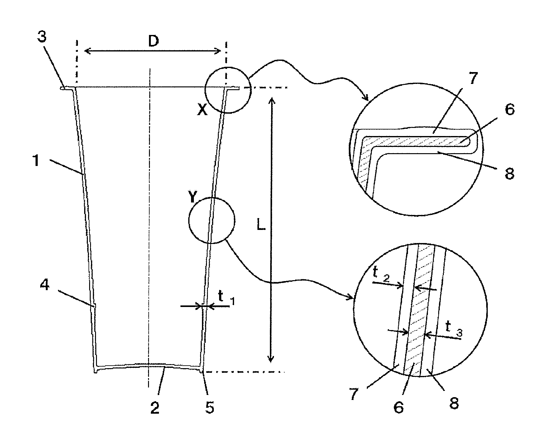
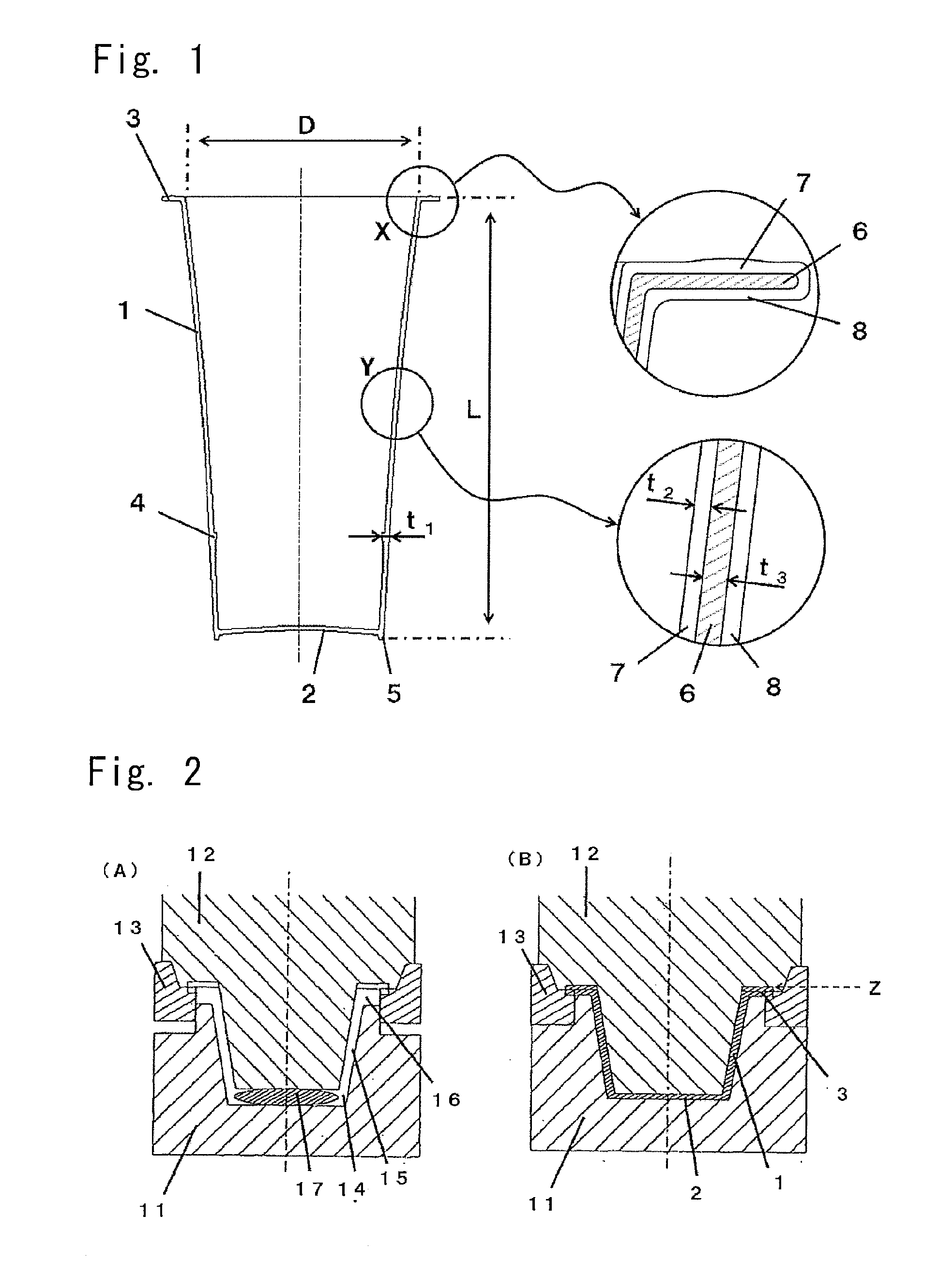
[0132]A random polypropylene resin (MFR 30 g / 10 min) was fed into a φ65 extruder (L / D=30), extruded through a nozzle of an outlet diameter of φ27 under the conditions of an extruder temperature of 230° C., die temperature of 230° C. and a resin pressure of 9.0 MPa, and was cut to obtain a molten resin mass. The molten resin mass was fed into a compression metal mold maintained at 18° C., compression-formed while defining, in advance, part of the flange, varying the thicknesses of the body portion of the container and of the portion that forms the bottom and controlling the forming rate to be 100 mm / sec at a point 5 mm before the point where the forming was completed to thereby obtain a single-layer cup-type container of a sectional structure as shown in FIG. 5(A) having a ratio L / D=1.6, a thickness in the body portion of the container of 1.0 to 1.6 mm, a container height of 95 mm, a container flange outer diameter of 59.3 mm, a volume of 120 cc and a weight of 12.8 g.

[0133]Next, the...

example 2

[0134]As a resin for forming inner and outer layers, a random polypropylene resin (MFR 30 g / 10 min) was fed into the 065 extruder (L / D=30), and was extruded under the conditions of an extruder temperature of 230° C. and a resin pressure of 9.0 MPa.

[0135]Further, an ethylene-vinyl alcohol copolymer resin was fed into a φ30 extruder (L / D=25) and was extruded under the conditions of an extruder temperature of 230° C. and a resin pressure of 30.0 MPa.

[0136]As an adhesive resin for adhering the intermediate layer to the inner and outer layers, further, a modified polypropylene resin was fed into a φ30 extruder (L / D=25) and was extruded under the conditions of an extruder temperature of 230° C. and a resin pressure of 22.0 MPa.

[0137]The inner and outer layers, intermediate layer and adhesive resin were met together in a die heated at 230° C., extruded through a nozzle of an outlet diameter of φ27, and was cut to obtain a multi-layer molten resin mass.

[0138]The multi-layer molten resin mas...

example 3

[0140]A random polypropylene resin (MFR 22 g / 10 min) was fed into a φ75 extruder (L / D=30), extruded through a nozzle of an outlet diameter of φ27 under the conditions of an extruder temperature of 220° C., a die temperature of 220° C. and a resin pressure of 1.2 MPa, and was cut to obtain a molten resin mass. The molten resin mass was compression-formed under the same forming conditions as those of Example 1 except that the temperature was 20° C. in the compression metal mold to which the molten resin mass was fed, and the forming rate was 300 mm / sec at a point 5 mm before the point where the forming was completed. There was obtained a single-layer cup-type container of the same shape as that of Example 1, which was then measured and evaluated in the same manner as in Example 1.


PUM

PropertyMeasurementUnit
thicknessaaaaaaaaaa
thicknessaaaaaaaaaa
heightaaaaaaaaaa

Abstract

A container obtained by compression-forming a thermoplastic resin includes a flange portion, a body portion and a bottom portion. A ratio (L / D) of the height of the container to the diameter of the opening is not less than 1.0, and if the direction of height of a test piece cut out from the body portion of the container is denoted by x and the circumferential direction thereof by y, a half-value width P at a half peak of a Miller index at a diffraction angle 2θ=14.5° that represents the diffraction by the crystal plane (110), is in a range of 1.25 to 1.5 over the whole body portion in a peak intensity profile in the direction of height (x-direction) of a Debye's ring obtained by measuring the diffraction intensities by causing the X-rays to be incident on an x-y plane of the test piece at right angles thereto.

Description

TECHNICAL FIELD[0001]This invention relates to a cup-type container and to a method of forming the same. More specifically, the invention relates to a cup-type container having improved heat resistance and improved mechanical strength such as shatter strength of the bottom portion and a method of forming the cup-type container.BACKGROUND ART[0002]As containers for containing beverages and foods, there have heretofore been widely used cup-type containers comprising a thermoplastic resin and having a body portion hanging down from the inner edge of the flange and a bottom portion.[0003]A variety of methods have been proposed for forming the cup-type containers, such as those methods that are usually based on the injection forming or the pressure forming. There has, further, been proposed a forming method based on the compression forming (patent document 1).[0004]However, a thin cup-type container made from a polypropylene by injection forming or pressure forming has a high degree of a...

Claims


Application Information

Patent Timeline
Patent Type & Authority Applications(United States)
IPC IPC(8): A47G19/22B29C43/20B29C43/02
CPCA47G19/2205B29C43/027B29K2905/00B29K2023/12B29C43/203B29C43/02B29C43/34B29C43/58B65D1/26B29C2043/5825B29C2043/5833B29L2031/7132B29K2995/0045
Inventor AZUMA, TOSHIFUSAASANO, YUTAKAUEDA, SHIGENORISHIMADA, MOTOHIKOYAMAGUCHI, MASARU
Owner TOYO SEIKAN GRP HLDG LTD
Learn More