Phosphor, light-emitting device including said phosphor, projector, head-up display and vehicle including said light-emitting device
a technology of light-emitting devices and phosphors, which is applied in the direction of fixed installations, lighting and heating apparatus, instruments, etc., can solve the problems of difficulty in realizing light-emitting devices with high efficiency, and achieve low enhance the effect of luminescence quantum efficiency of sms phosphors and low efficiency
- Summary
- Abstract
- Description
- Claims
- Application Information
AI Technical Summary
Benefits of technology
Problems solved by technology
Method used
Image
Examples
first embodiment
[0031]The first embodiment is directed to a phosphor which includes Sr3MgSi2O8 crystal and SrMgSiO4 crystal as a host crystal and also includes Eu2+, or Eu2+ and Mn2+ as luminescent centers.
[0032]After extensive studies, the present inventors have found that Sr3MgSi2O8:Eu2+ phosphors in which the host crystal is a mixed crystal of Sr3MgSi2O8 and SrMgSiO4 (namely, a Sr3MgSi2O8 crystal phase and a SrMgSiO4 crystal phase are present in a single crystal grain) exhibit higher luminescence quantum efficiency than Sr3MgSi2O8:Eu2+ phosphors whose host crystal is a single Sr3MgSi2O8 crystal phase.
[0033]The presence of the two types of crystals, namely, the Sr3MgSi2O8 crystal and the SrMgSiO4 crystal in the host crystal of the phosphor may be confirmed by, for example, measuring an X-ray diffraction pattern of the phosphor. When, for example, the phosphor of the present embodiment is analyzed by X-ray diffractometry using Cu—Kα radiation, the diffraction pattern has diffraction peaks at 2θ of...
second embodiment
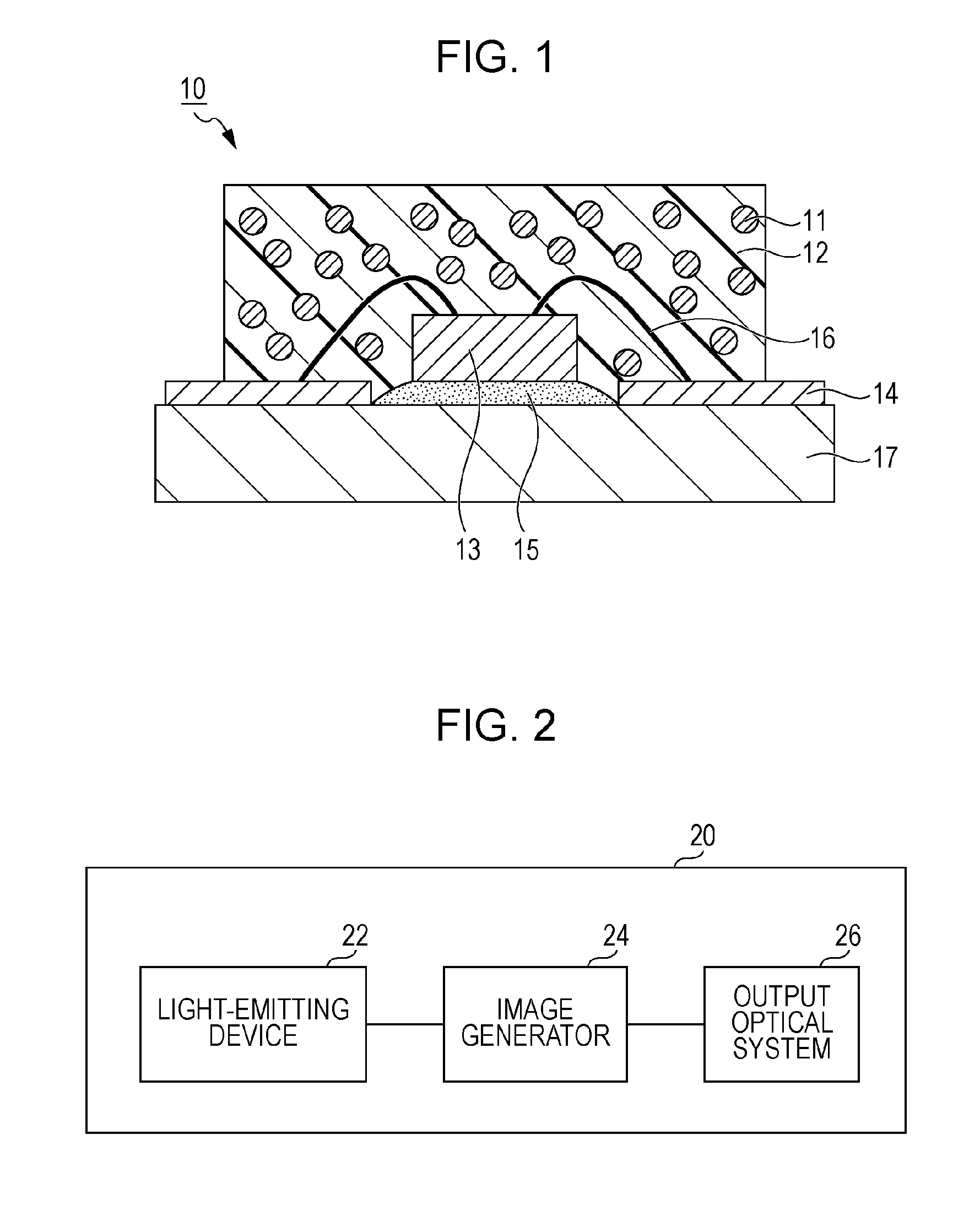
[0051]The second embodiment is directed to a light-emitting device that includes a phosphor layer containing the phosphor of the first embodiment. Examples of the light-emitting devices include those devices which use light-emitting diodes (LEDs) or semiconductor laser diodes (LDs) and phosphors, specifically, light sources for projection units such as projectors and head-up displays; light sources for vehicle headlights; light sources for white LED lights such as spot lights, ceiling lights and vehicle room lamps; flash light sources for image recording apparatuses such as digital cameras, mobile phones and smart phones; and backlight sources for liquid crystal displays such as personal computer (PC) monitors, notebook personal computers, televisions, personal digital assistances (PDAs), smart phones, tablet PCs and mobile phones; as well as include those devices which use phosphors, specifically, sensors, intensifiers and plasma display panels (PDPs).
[0052]A specific configuration...
third embodiment
[0057]The third embodiment is directed to a projection unit including the light-emitting device of the second embodiment. For example, the projection unit is a projector or a head-up display.
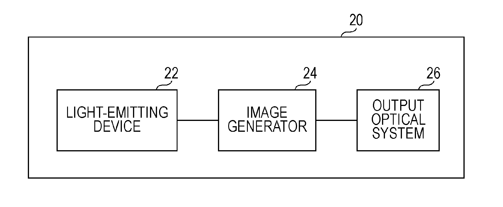
[0058]A specific configuration of the projection units of the third embodiment will be described below with reference to the drawing, but the scope of the present disclosure is not limited to such a configuration. FIG. 2 is a schematic view illustrating an exemplary configuration of a projection unit 20 according to the third aspect. The projection unit 20 includes a light-emitting device 22 defining a light source section, an image generator 24 and an output optical system 26.
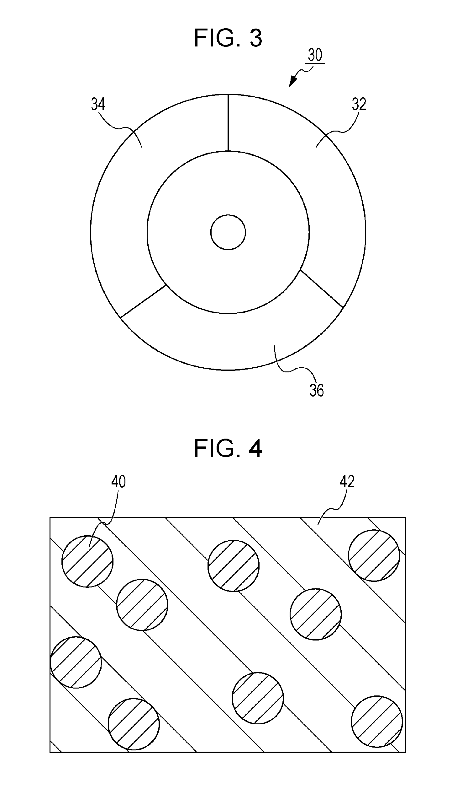
[0059]The light-emitting device 22 is the light-emitting device of the second embodiment. Specifically, for example, the light-emitting device 22 includes an excitation light source and a color wheel 30.
[0060]For example, the excitation light source may be a semiconductor light-emitting element (such as an LD or an LED) th...
PUM
| Property | Measurement | Unit |
|---|---|---|
| 2θ | aaaaa | aaaaa |
| 2θ | aaaaa | aaaaa |
| 2θ | aaaaa | aaaaa |
Abstract
Description
Claims
Application Information
 - R&D
- Intellectual Property
- Life Sciences
- Materials
- Tech Scout
- Unparalleled Data Quality
- Higher Quality Content
- 60% Fewer Hallucinations
Browse by: Latest US Patents, China's latest patents, Technical Efficacy Thesaurus, Application Domain, Technology Topic, Popular Technical Reports.
© 2025 PatSnap. All rights reserved.Legal|Privacy policy|Modern Slavery Act Transparency Statement|Sitemap|About US| Contact US: help@patsnap.com


