SiOx BARRIER FOR PHARMACEUTICAL PACKAGE AND COATING PROCESS

a technology of siox barrier and pharmaceutical package, which is applied in the direction of chemical vapor deposition coating, container/bottle contruction, rigid containers, etc., can solve the problems of insufficient stability, damage to stored materials, and non-uniform surface chemistry at the molecular level

Inactive Publication Date: 2015-10-22
SI02 MEDICAL PRODS
View PDF1 Cites 22 Cited by
  • Summary
  • Abstract
  • Description
  • Claims
  • Application Information

AI Technical Summary

Benefits of technology

[0047]The vessel has a pH protective coating or layer of SiOxCy, in which x is between 0.5 and 2.4 and y is between 0.6 and 3. The pH protective coating or layer is applied by PECVD, is positioned between the composite barrier coating or layer and the fluid and is s...

Problems solved by technology

However, the recent advent of costly, complex and sensitive biologies as well as such advanced delivery systems as auto injectors has exposed the physical and chemical shortcomings of glass pharmaceutical packages or other vessels, including possible contamination from metals, flaking, and breakage, among other problems.
Moreover, glass contains several components which can leach out during storage and cause damage to the stored material.
The heterogeneous nature of borosilicate glass creates a non-uniform surface chemistry at the molecular level.
Many proteins and other biologies must be lyophilized (freeze dried), because they are not sufficiently stable in solution in glass vials or syringes.
Glass pharmaceutical packages or other vessels are prone to breakage or degradation during manufacture, filling operations, shipping and use, which means that glass particulates may enter the drug.
Glass-forming processes do not yield the tight dimensional tolerances required for some of the newer au...

Method used


Image

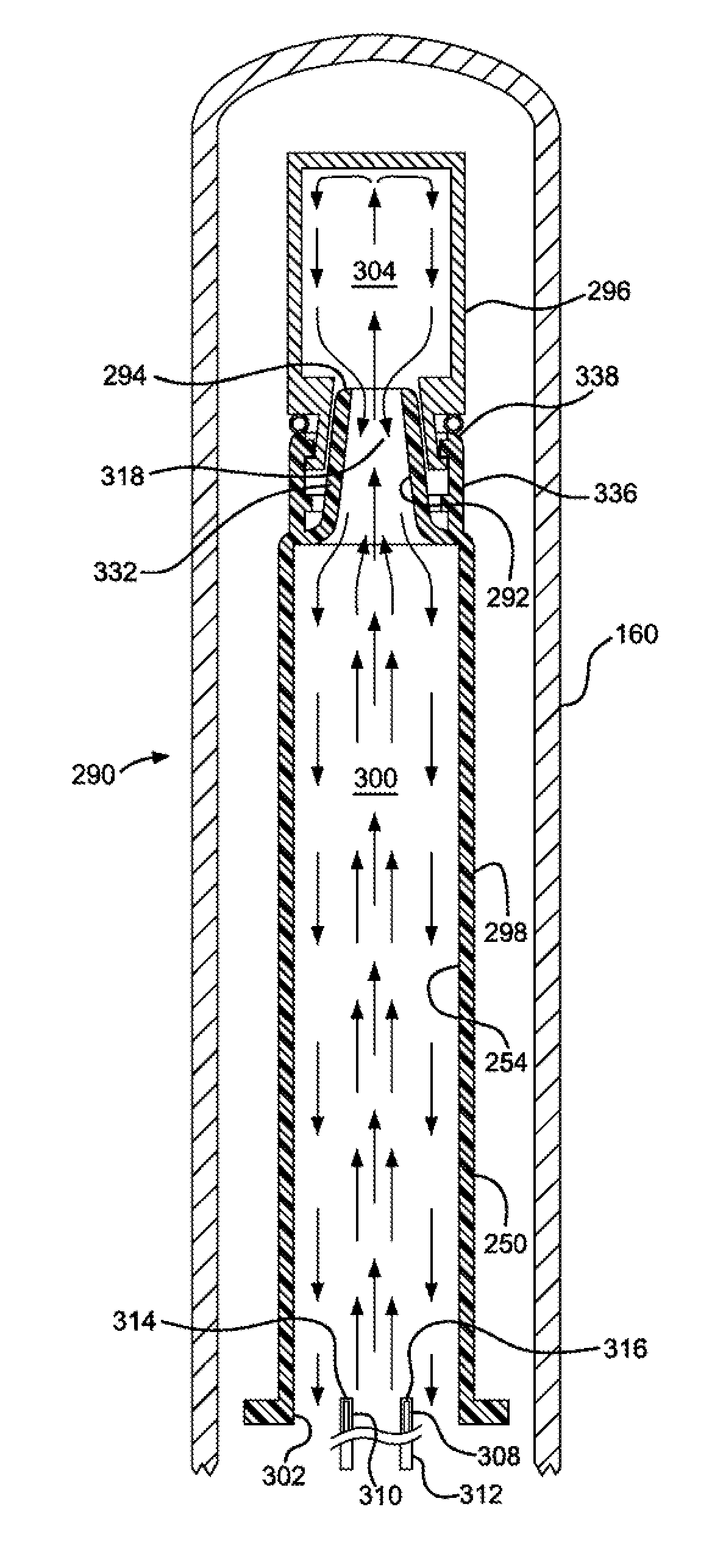
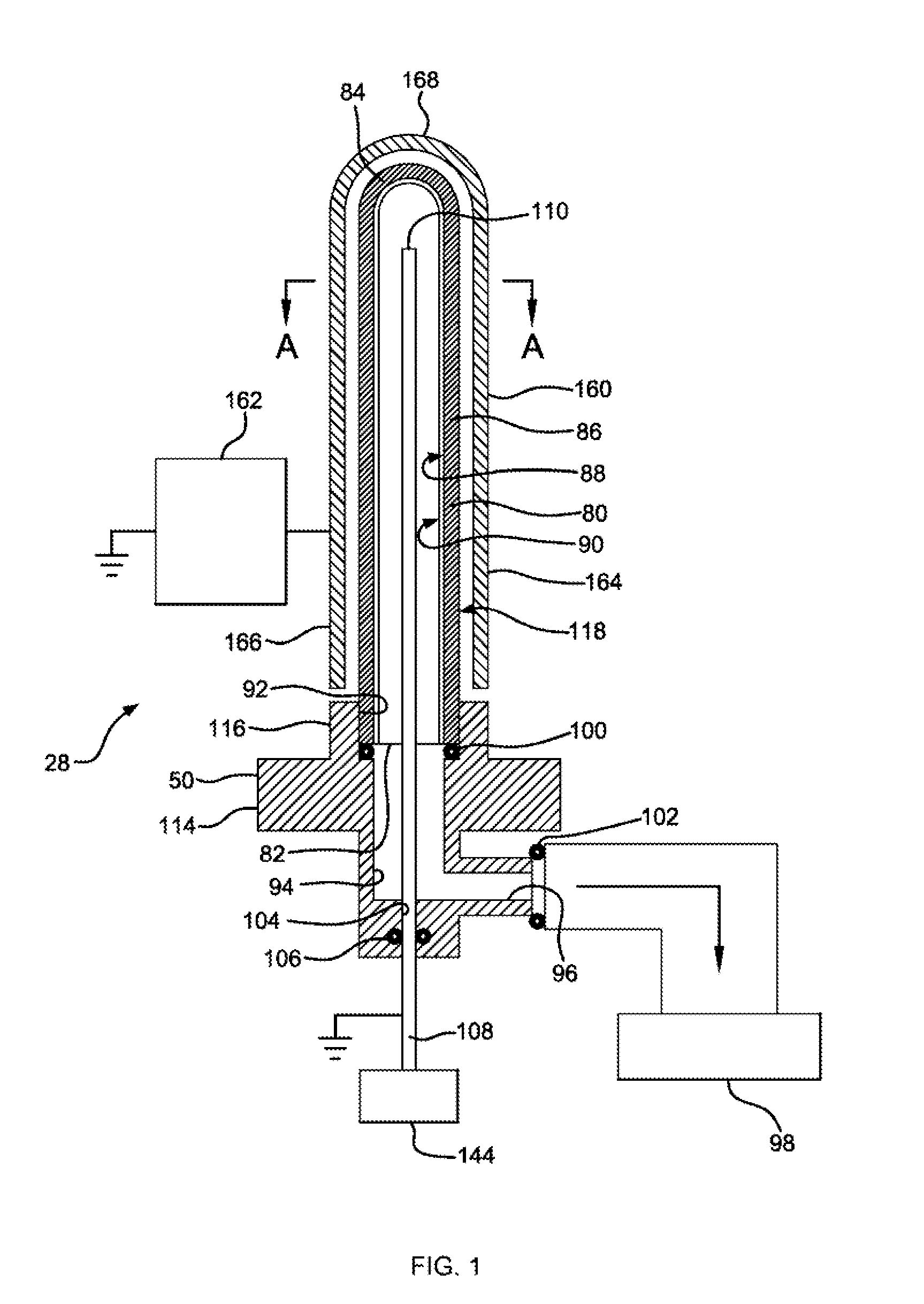
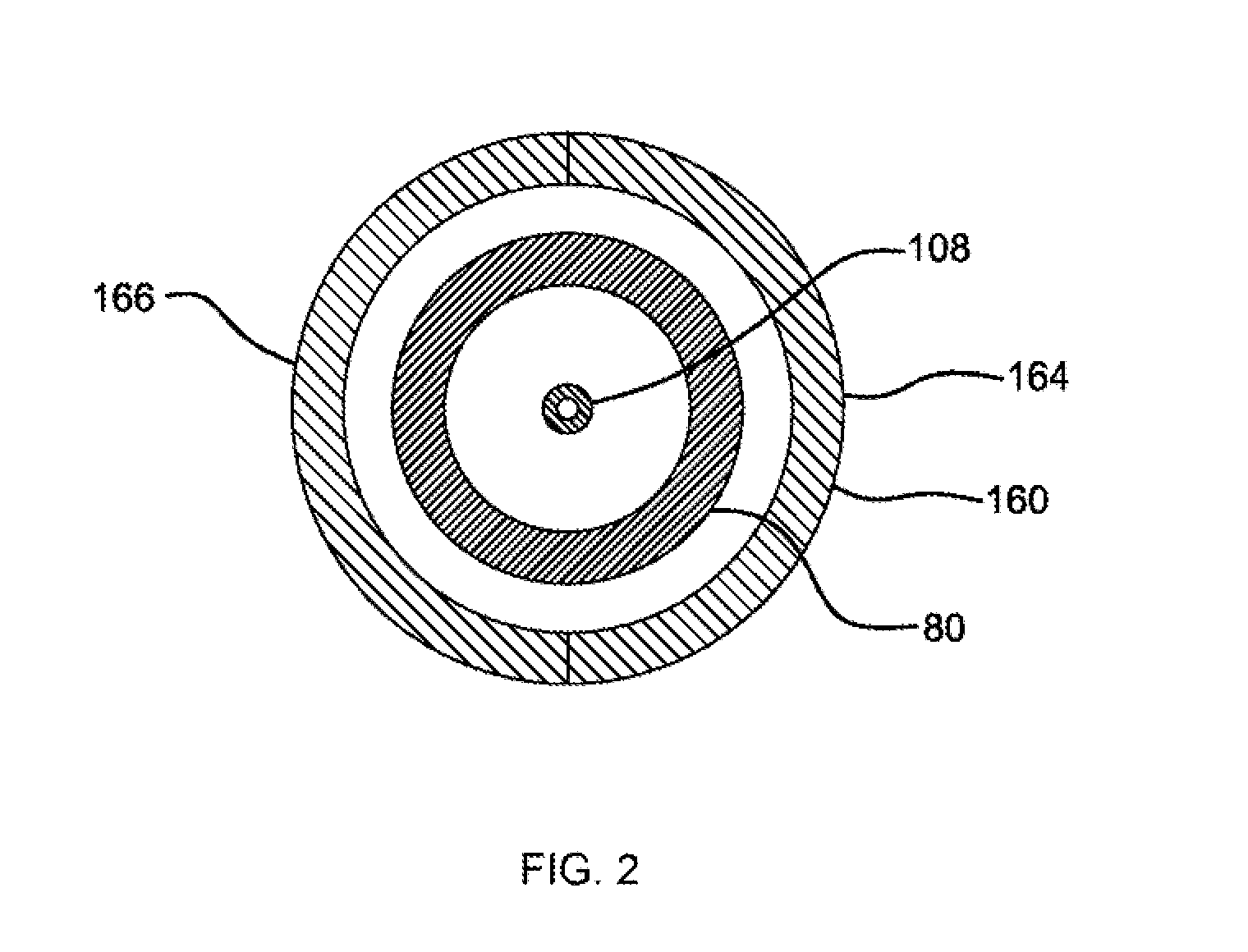
  • SiOx BARRIER FOR PHARMACEUTICAL PACKAGE AND COATING PROCESS
  • SiOx BARRIER FOR PHARMACEUTICAL PACKAGE AND COATING PROCESS
  • SiOx BARRIER FOR PHARMACEUTICAL PACKAGE AND COATING PROCESS

Examples


examples

[0668]The following Examples are in part already disclosed in EP 2 251 455. In order to avoid unnecessary repetition, not all of the Examples in EP 2 251 455 A2 are repeated here, but explicit reference is herewith made to them.

Basic Protocols for Forming and Coating Syringe Barrels

[0669]The pharmaceutical packages or other vessels tested in the subsequent working examples were formed and coated according to the following exemplary protocols, except as otherwise indicated in individual examples. Particular parameter values given in the following basic protocols, for example the electric power and gaseous reactant or process gas flow, are typical values. When parameter values were changed in comparison to these typical values, this will be indicated in the subsequent working examples. The same applies to the type and composition of the gaseous reactant or process gas.

[0670]In some instances, the reference characters and Figures mentioned in the following protocols and additional deta...

examples 1-4

[0692]Syringe samples were produced as follows. A COC 8007 extended barrel syringe was produced according to the Protocol for Forming COC Syringe Barrel. An SiOx barrier coating or layer is applied to some of the syringes according to the Protocol for coating COC Syringe Barrel Interior with SiOx. A lubricity and / or pH protective coating or layer is applied to the SiOx coated syringes according to the Protocol for Coating COC Syringe Barrel Interior with OMCTS Lubricity Coating, modified as follows. The OMCTS was supplied from a vaporizer, due to its low volatility. Argon carrier gas was used. The process conditions were set to the following:[0693]OMCTS—3 sccm[0694]Argon gas—65 sccm[0695]Power—6 watts[0696]Time—10 seconds

[0697]Several syringes are then tested for lubricity using a Genesis Packaging Plunger Force Tester (Model SFT-01 Syringe Force Tester, manufactured by Genesis Machinery, Lionville, Pa.) according to the Protocol for Lubricity Testing. Both the initiation force and ...

examples 5-8

[0700]Syringe samples are produced as follows. A COC 8007 extended barrel syringe was produced according to the Protocol for Forming COC Syringe Barrel. An SiOx pH protective coating or layer is applied to the syringe barrels according to the Protocol for Coating COC Syringe Barrel Interior with SiOx. A lubricity and / or pH protective coating or layer is applied to the SiOx coated syringes according to the Protocol for Coating COC Syringe Barrel Interior with OMCTS, modified as follows. Argon carrier gas and oxygen are used where noted in Table 6. The process conditions are set to the following, or as indicated in Table 6:[0701]OMCTS—3 sccm (when used)[0702]Argon gas—7.8 sccm (when used)[0703]Oxygen 0.38 sccm (when used)[0704]Power—3 watts[0705]Power on time—10 seconds

[0706]The syringes of Examples 5 and 6 prepared under these conditions. The syringes of Example are 7 prepared under these conditions except without a lubricity and / or pH protective coating or layer, and the syringes of...


PUM

PropertyMeasurementUnit
Temperatureaaaaaaaaaa
Lengthaaaaaaaaaa
Fractionaaaaaaaaaa

Abstract

A vessel including a thermoplastic wall enclosing a lumen is disclosed. The wall supports an SiOx composite barrier coating or layer, for which x is from 1.8 to 2.4, between the wall and the lumen. High Resolution X-ray Photoelectron Spectroscopy (XPS) shows the presence of an interface between the composite barrier coating or layer and the wall or substrate. In one aspect, the interface has at least 1 mol.% O3—Si—C covalent bonding, as a proportion of the O3—Si—C covalent bonding plus SiO4 bonding. In another aspect, the interface has an Si 2p chemical shift to lower binding energy (eV), compared to the binding energy of SiO4 bonding. The result is a tightly adherent composite barrier coating or layer having a high degree of adhesion to the substrate under practical use conditions. Methods of applying the composite barrier coating or layer are also disclosed.

Description

[0001]Priority is claimed from U.S. Ser. Nos. 61 / 667,871, filed Jul. 3, 2012, and 61 / 800,746, filed Mar. 15, 2013, and this application is a continuation-in-part of U.S. Ser. No. 13 / 169,811, filed Jun. 27, 2011, now pending, which is a divisional of U.S. Ser. No. 12 / 779,007, filed May 12, 2010, now U.S. Pat. No. 7,985,188, which claims priority to U.S. Provisional Ser. Nos. 61 / 222,727, filed Jul. 2, 2009; 61 / 213,904, filed Jul. 24, 2009; 61 / 234,505, filed Aug. 17, 2009; 61 / 261,321, filed Nov. 14, 2009; 61 / 263,289, filed Nov. 20, 2009; 61 / 285,813, filed Dec. 11, 2009; 61 / 298,159, filed Jan. 25, 2010; 61 / 299,888, filed Jan. 29, 2010; 61 / 318,197, filed Mar. 26, 2010, and 61 / 333,625, filed May 11, 2010. The above patent and applications are incorporated here by reference in their entirety.[0002]U.S. Pat. No. 7,985,188; International Application PCT / US11 / 36097, filed May 11, 2011; U.S. Ser. No. 61 / 558,885, filed Nov. 11, 2011; and U.S. Ser. No. 61 / 636,377, filed Apr. 20, 2012, are all in...

Claims


Application Information

Patent Timeline
IPC IPC(8): A61L31/08B65D65/42A61M15/00A61M5/178A61J1/05A61L31/04A61F9/00A61M35/00A61M5/00A61L31/16A61L31/14A61J1/03A61J7/00
CPCA61L31/088A61J1/035B65D65/42A61M15/0001A61M5/178A61J1/05A61L2420/02A61F9/0008A61M35/003A61M5/007A61L31/16A61L31/14A61L31/048A61J7/0053A61M5/3129A61M2202/048A61M2205/0238A61M2205/19A61L29/106A61J1/1468C23C16/401
Inventor WEIKART, CHRISTOPHERFELTS, JOHN T.FISK, THOMAS E.ABRAMS, ROBERT S.FERGUSON, JOHNFREEDMAN, JONATHAN R.PANGBORN, ROBERT J.SAGONA, PETER J.
Owner SI02 MEDICAL PRODS
Why Eureka
Try Eureka