Low complexity partial parallel architectures for fourier transform and inverse fourier transform over subfields of a finite field

a partial parallel architecture and subfield technology, applied in the field of architectures for fourier transforms and inverse fourier transforms, can solve the problems of large area requirements associated with the 1-parallel chien search architecture complex and computationally intensive architectures, etc., and achieve the effect of reducing complexity and broad applications

Inactive Publication Date: 2015-10-22
WODEN TECH INC
View PDF8 Cites 20 Cited by
  • Summary
  • Abstract
  • Description
  • Claims
  • Application Information

AI Technical Summary

Benefits of technology

[0004]Techniques are disclosed for performing Fourier transforms and inverse Fourier transforms over a subfield of a finite field. The use of a Fourier transform, such as a finite field Fourier transform (FT) and an inverse Fourier transform, such as an inverse finite field Fourier transform (IFT), may have broad applications in error-correcting coding, such as low-density parity check (LDPC) codes and Reed-Solomon codes. The techn...

Problems solved by technology

These architectures may have fully parallel inputs and fully parallel outputs which make the architectures (e.g., fully paralleled architectures) complex and computationally intensive.
Previous Fourier transforms for finite fields and inverse field Fourier transforms for finite fields have been fully parallel (e.g., fully parallel inputs and outputs) with VLSI architectures that are complex and computationally intensive.
Although constant multipliers may be less complicated than general multipliers, such a large number of constant multipliers and adders over GF(2r) would lead to large area requirement associated with ...

Method used


Image

  • Low complexity partial parallel architectures for fourier transform and inverse fourier transform over subfields of a finite field
  • Low complexity partial parallel architectures for fourier transform and inverse fourier transform over subfields of a finite field
  • Low complexity partial parallel architectures for fourier transform and inverse fourier transform over subfields of a finite field

Examples


Embodiment Construction

[0011]Particular embodiments of the present disclosure are described below with reference to the drawings. In the description, common features may be designated by common reference numbers throughout the drawings.

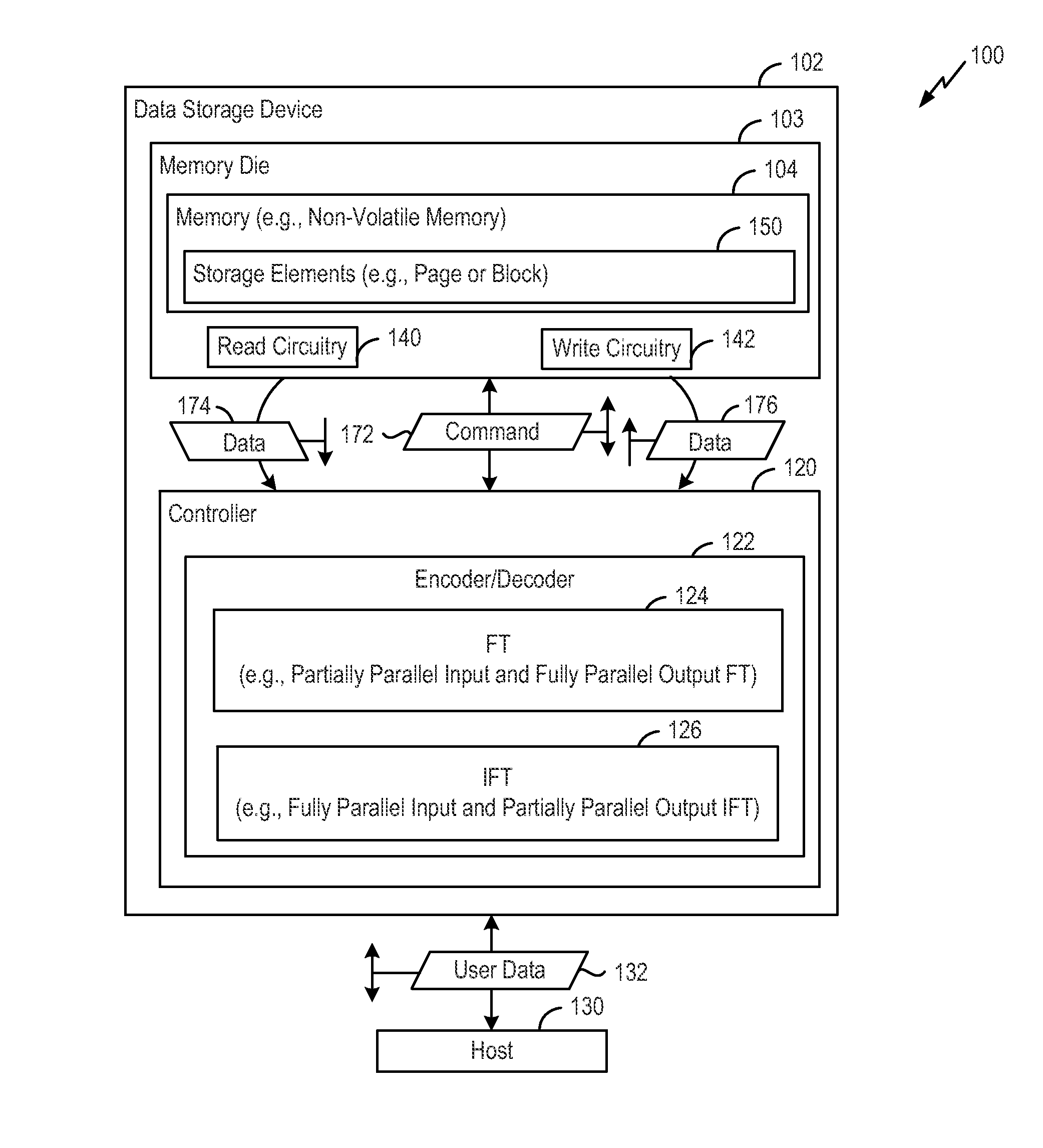
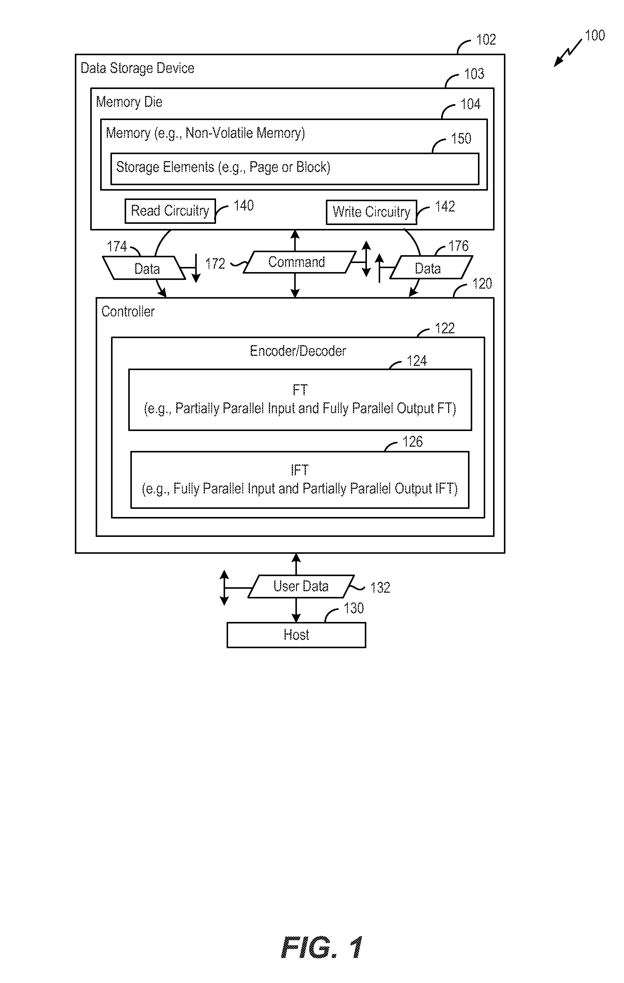
[0012]FIG. 1 is a block diagram of a particular illustrative embodiment of a system 100 including a data storage device 102 coupled to an accessing device, such as a host device 130. The data storage device 102 may be coupled to the host device 130 via a communication path, such as a wired communication path and / or a wireless communication path. The data storage device 102 may be embedded within the host device 130, such as in accordance with an embedded MultiMedia Card (eMMC®) (trademark of Joint Electron Devices Engineering Council (JEDEC) Solid State Technology Association, Arlington, Va.) configuration. Alternatively, the data storage device 102 may be removable from (i.e., “removably” coupled to) the host device 130. For example, the data storage device 102 may be remo...


PUM


Abstract

Low complexity partial parallel architectures for performing a Fourier transform and an inverse Fourier transform over subfields of a finite field are described. For example, circuits to perform the Fourier transforms and the inverse Fourier transform as described herein may have architectures that have simplified multipliers and/or computational units as compared to traditional Fourier transform circuits and traditional inverse Fourier transform circuits that have partial parallel designs. In a particular embodiment, a method includes, in a data storage device including a controller and a non-volatile memory, the controller includes an inverse Fourier transform circuit having a first number of inputs coupled to multipliers, receiving elements of an input vector and providing the elements to the multipliers. The multipliers are configured to perform calculations associated with an inverse Fourier transform operation. The first number is less than a number of inverse Fourier transform results corresponding to the inverse Fourier transform operation.

Description

FIELD OF THE DISCLOSURE[0001]The present disclosure is generally related to architectures for Fourier transforms and inverse Fourier transforms.BACKGROUND[0002]Non-volatile data storage devices, such as embedded memory devices (e.g., embedded MultiMedia Card (eMMC) devices) and removable memory devices (e.g., removable universal serial bus (USB) flash memory devices and other removable storage cards), have allowed for increased portability of data and software applications. Users of non-volatile data storage devices increasingly rely on the non-volatile storage devices to store and provide rapid access to a large amount of data.[0003]Fourier transforms and inverse Fourier transforms have been adopted in various technologies, such as data storage, signal processing, and communication systems. For example, architectures, such as very large scale integration (VLSI) architectures, have been developed for a Fourier transform and an inverse Fourier transform. These architectures may have ...

Claims


Application Information

Patent Timeline
IPC IPC(8): G06F17/14
CPCG06F17/14G06F17/141H03M13/1171H03M13/1515H03M13/152H03M13/1545H03M13/158H03M13/6561
Inventor ZHANG, XINMIAOTAI, YING YU
Owner WODEN TECH INC
Why Eureka
Try Eureka