Miniaturized Patch Antenna

a patch antenna and antenna technology, applied in simultaneous aerial operations, electrical equipment, structural forms of radiation elements, etc., can solve the problems of large antenna size, poor efficiency, narrow bandwidth, etc., and achieve the effect of improving the symmetry of the radiation pattern of the antenna

Inactive Publication Date: 2015-10-22
TAGSYS +1
View PDF8 Cites 41 Cited by
  • Summary
  • Abstract
  • Description
  • Claims
  • Application Information

AI Technical Summary

Benefits of technology

[0005]According to the invention, it is proposed to etch a slot near the centre of patch structure of the antenna, said slot surrounding the centre of the patch, in order to concentrate the surface current distribution at the centre of the patch structure and, as a result, to reduce the size of the patch structure.
[0010]As it will be shown in the detailed description to be followed, the presence of this first slot modifies the distribution of the currents at the surface of the patch structure and concentrates them at the centre of the patch structure. As a consequence, the area of the patch structure can be reduced without decreasing significantly the gain of the antenna.
[0013]In another embodiment, the patch antenna further comprises a second slot etched in the patch structure, said second slot surrounding the feeding point. The function of this second slot is to improve the symmetry of the radiation pattern of the antenna compared to an axis perpendicular to the plane of the patch.

Problems solved by technology

But one of the problems is its large size especially in UHF frequency bands.
The antenna size reductions achieved by using these techniques are generally small and suffer from significantly from poor efficiency and narrow bandwidth.
In addition, patch antennas directly fabricated on high dielectric-constant substrates suffer from surface-wave effects that can severally degrade the performance of the antenna.
The excitation of surface waves not only contaminates the radiation pattern (containing dips near the maximum and significant sidelobes) and reduces the efficiency of the radiating element, but also can cause unwanted coupling between the active devices within the module.
These antennas suffer from the degradation of some characteristics, notably their gain.

Method used


Image

  • Miniaturized Patch Antenna
  • Miniaturized Patch Antenna
  • Miniaturized Patch Antenna

Examples


first embodiment

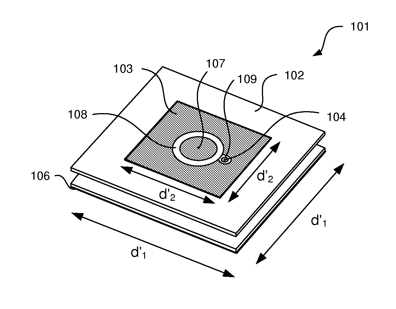
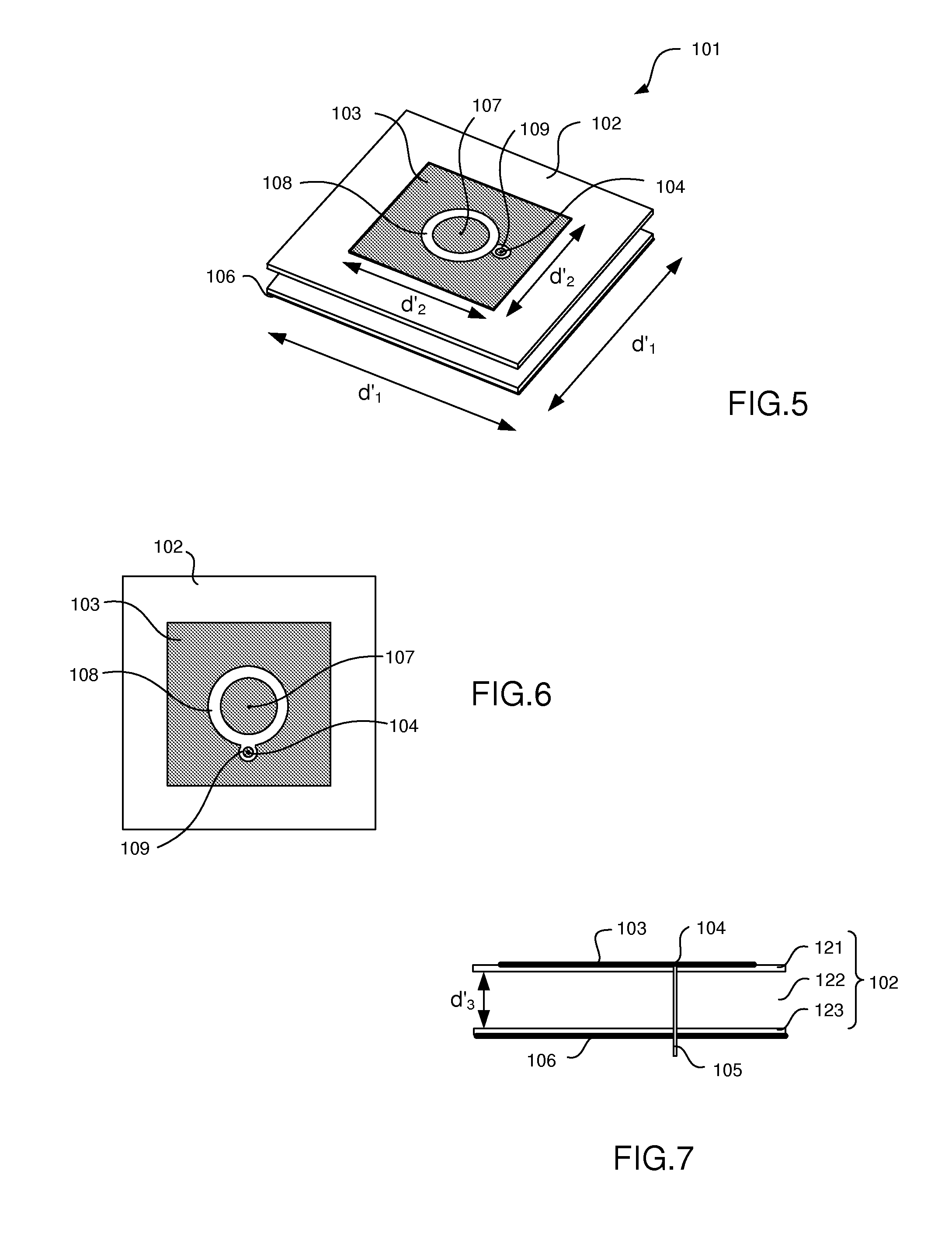
[0073]the patch antenna assembly according to the invention is illustrated by FIGS. 5-10.

[0074]In this first embodiment, the patch antenna comprises two slotted rings etched in the patch structure, one surrounding the centre of the patch structure and one surrounding the feeding point.

[0075]In reference to FIGS. 5-7, the patch antenna assembly 101 according to this first embodiment comprises:[0076]a multilayered dielectric or magnetic substrate 102 including at least a top layer 121, a middle layer 122 and a bottom layer 123,[0077]an electrically conductive patch structure 103 on the upper surface of the top layer, the patch structure having a centre point 107 located at the centre of the patch structure a feeding point 104 electrically coupled to a feed line 105, and[0078]a ground plane 106 on the lower surface of the bottom layer.

[0079]The top layer 121 and the bottom layer 123 are made of FR4 or other substrate type having the same parameters than the top layer 21 and the bottom ...

second embodiment

[0100]The central ring can also be moved away from the feed ring. It is illustrated by FIG. 11 and FIG. 12. In this second embodiment, the central ring and the feed ring 109 have outer diameters D and d and widths W and w, respectively and they are separated from each other by a non-zero distance e. The distance e is a function of the parameters D, d, W and w.

[0101]The resonance frequency of the antenna assembly is depending on the parameters D and W of the central ring. More specifically, the width W of the central ring has an effect on the inductance of the antenna and its diameter has an effect on the capacitance of the antenna. The width W of the central ring can vary from 2 mm to 12 mm and the diameter D from 2 cm to 4.5 cm. In the configuration of the FIGS. 5 to 7, the resonance frequency of 866.3 MHz (inside the UHF band) is obtained by a width W=8 mm and D=4 cm.

[0102]The width w and the diameter d of the feed ring have little influence on the resonance frequency.

third embodiment

[0103]As mentioned hereinabove, the feed ring has no influence on the size of the patch antenna. Consequently, in a third embodiment illustrated by FIG. 13, the antenna assembly does not have feed ring. The central ring alone is enough to reduce the size of the antenna structure. This central ring is not necessarily circular but may be elliptic.

[0104]The central slotted ring must concentrate the surface current at the centre of the patch structure 103. This central slot is not necessarily a ring. This slot can have different shapes as illustrated by FIGS. 14-17. This slot must surround the centre point of the patch structure 103. Preferably, this slot is centered on the centre point of the patch structure.

[0105]In FIG. 14, the central slot is a square centered on the centre point of the patch structure, in FIG. 15, the central slot is a hexagon and in FIG. 16, the central slot is a triangle. The feeding point can be surrounded by a slot 109 or not. The shape of the slot 109 is prefe...


PUM


Abstract

The present invention relates to a miniaturized patch antenna assembly in UHF frequency band. The invention is notably useful in RFID applications. The patch antenna assembly includes a multilayered dielectric substrate including at least a top layer, a middle layer and a bottom layer, an electrically conductive patch structure on the upper surface of the top layer, the patch structure having a center point located at the center of patch structure surface and a feeding point electrically coupled to a feed line, a ground plane on the lower surface of the bottom layer. The assembly can include a slot etched in the patch structure, the slot surrounding the center point of the patch structure. This slot aims to concentrate the surface current at the center of the patch structure, which allows reducing its size.

Description

TECHNICAL FIELD[0001]The present invention relates to a miniaturized technique of patch antenna in UHF frequency band. It can be applied in particular, but not exclusively, in wireless communication systems in which the miniaturization of the antenna is sought without degrading its gain. The invention is notably useful in RFID applications.BACKGROUND OF THE INVENTION[0002]The explosive growth of wireless communication systems has led to an increasing demand for a compact size low-cost antenna. Patch antennas have a planar structure, suitable for integration on a multilayered material. But one of the problems is its large size especially in UHF frequency bands. RFID application demands high gain compact size antenna. So it is important to design antennas with high gain but of compact size although both of them are mutually conflicting properties. Several miniaturization techniques have been identified, in particular for printed low-profile antennas. These include the use of high diel...

Claims


Application Information

Patent Timeline
Patent Type & Authority Applications(United States)
IPC IPC(8): H01Q9/04H01Q1/38
CPCH01Q1/38H01Q9/0407H01Q1/2208H01Q9/0442H01Q9/0464
Inventor LATRACH, MOHAMEDD'ANNUNZIO, FRANCK
Owner TAGSYS
Why Eureka
Try Eureka