Motor control apparatus and motor control method
a technology of motor control and control apparatus, which is applied in the direction of motor/generator/converter stopper, dynamo-electric converter control, transportation and packaging, etc., can solve problems such as vibration in the vehicle body, and achieve the effect of rapid output torqu
- Summary
- Abstract
- Description
- Claims
- Application Information
AI Technical Summary
Benefits of technology
Problems solved by technology
Method used
Image
Examples
first embodiment
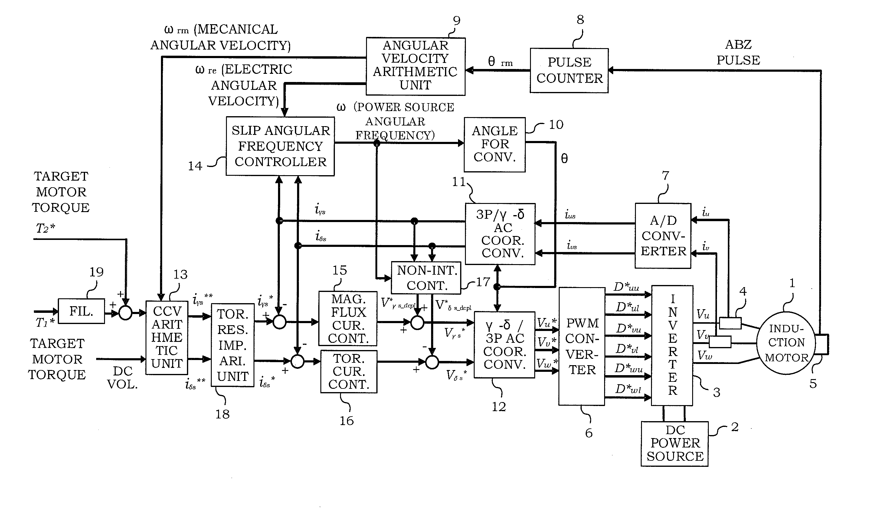
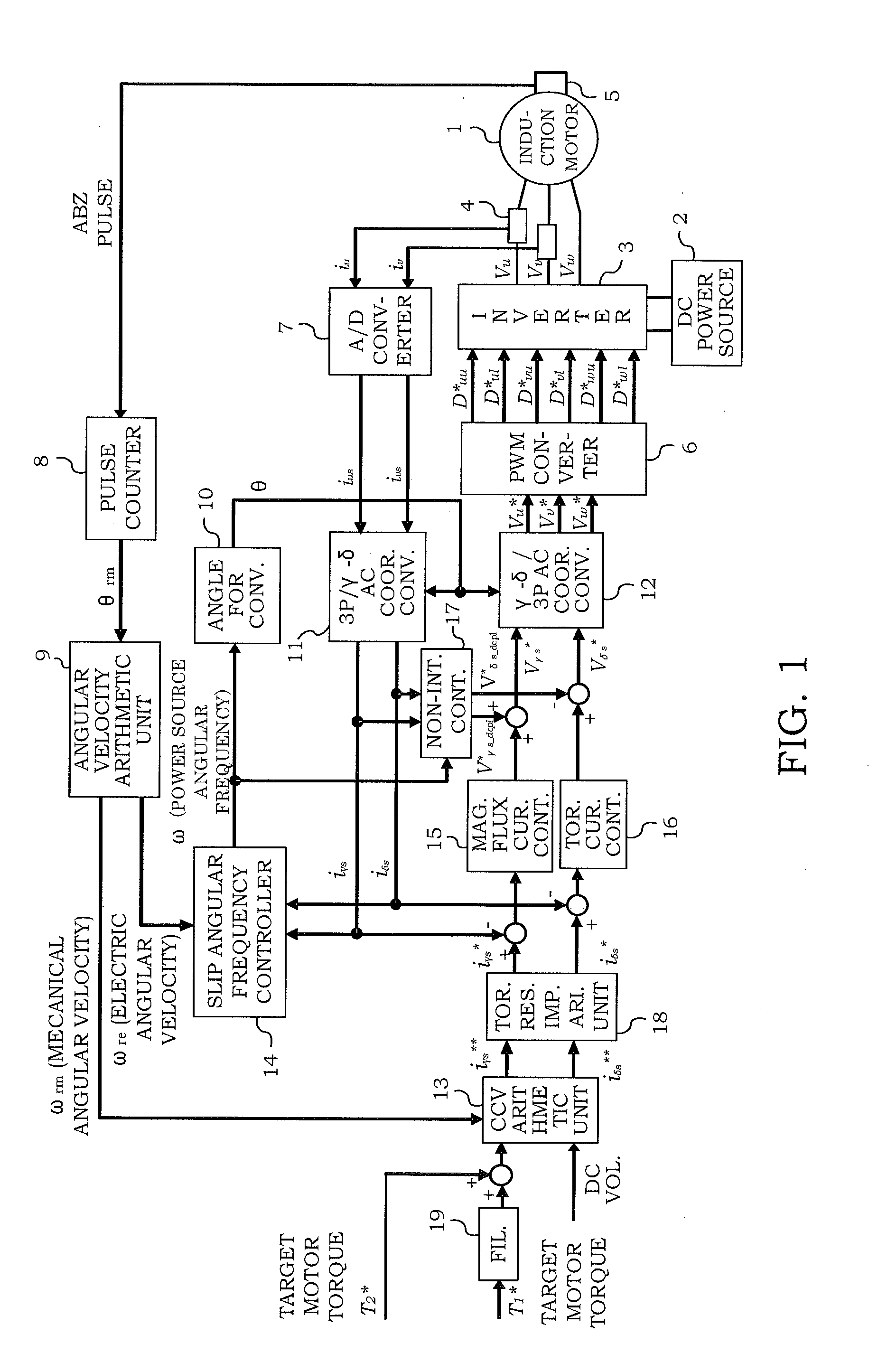
[0032]FIG. 1 is a block diagram showing a configuration of a motor control apparatus according to a first embodiment. This motor control apparatus is applied to an electric vehicle, for example. It should be noted that the motor control apparatus can be applied to a hybrid vehicle or a system other than a vehicle, for example, in addition to the electric vehicle.
[0033]A motor 1 is a three-phase AC induction motor. In a case where the motor control apparatus is applied to an electric vehicle, the motor 1 becomes a driving source of the vehicle.
[0034]A PWM convertor 6 generates PWM_Duty driving signals Duu*, Dul*, Dvu*, Dvl*, Dwu*, Dwl* for switching elements (such as an IGBT) in a three-phase voltage type inverter 3 on the basis of three-phase voltage command values Vu*, Vv*, Vw*.
[0035]The inverter 3 converts a DC voltage of a DC power source 2 into AC voltages Vu, Vv, Vw on the basis of the driving signals generated by the PWM convertor 6, and supplies the AC voltages to the motor 1...
second embodiment
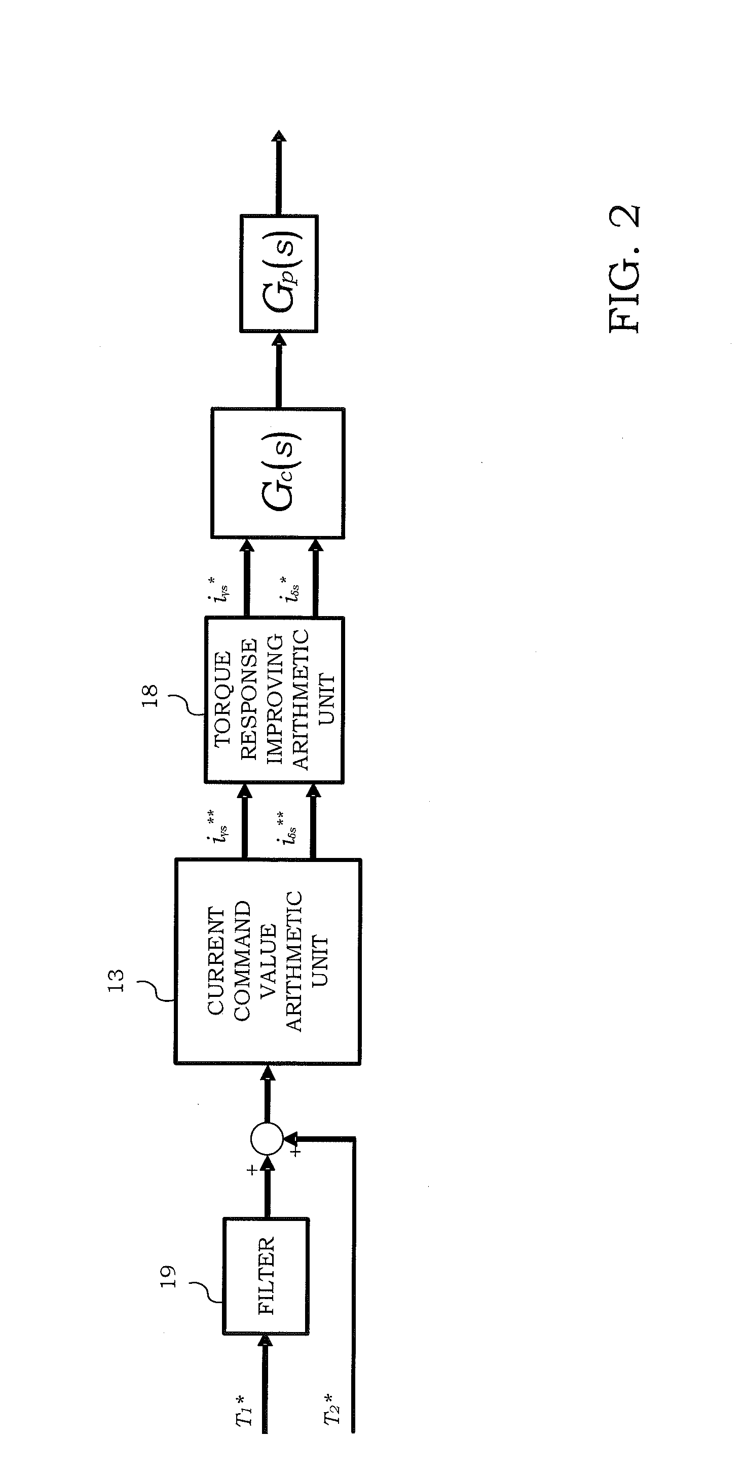
[0078]FIG. 12 is a block diagram showing a main configuration of a motor control apparatus according to a second embodiment, and corresponds to FIG. 2 in the first embodiment. As well as the configuration shown in FIG. 2, an induction motor is adopted as the motor 1. The same reference numerals are provided to the elements similar to the configuration shown in FIG. 2, and their detailed explanation will be omitted.
[0079]In the motor control apparatus according to the second embodiment, a limiter 30 is provided in the subsequent stage of the torque response improving arithmetic unit 18. The limiter 30 carries out processing to limit the δ-axis current command value iδs* outputted from the torque response improving arithmetic unit 18 to an upper limit value iδs—lim. The upper limit value iδs—lim is expressed by the following formula (16) on the basis of the maximum value Is—max of the current of the motor 1 and the γ-axis current command value iγs*.
[Formula 16]
iδs—lim=√{square root ov...
third embodiment
[0086]In a motor control apparatus according to a third embodiment, even though a target motor torque obtained by adding the target motor torque T1* for which the delay processing was carried out by the filter 19 to the target motor torque T2* is zero or in the vicinity of zero (a predetermined torque or lower), a current to generate magnetic flux at the rotor side is outputted by a predetermined amount greater than zero.
[0087]FIG. 16 is a block diagram showing a main configuration of the motor control apparatus according to the third embodiment. The same reference numerals are provided to the same elements as those of the configuration shown in FIG. 2, and their detailed explanation will be omitted.
[0088]In the motor control apparatus according to the third embodiment, a lower limit limiter 60 is provided in the subsequent stage of the current command value arithmetic unit 13. The lower limit limiter 60 carries out limiter processing in which the γ-axis current command value iγs fr...
PUM
 Abstract
Description
Claims
Application Information
 - R&D
- Intellectual Property
- Life Sciences
- Materials
- Tech Scout
- Unparalleled Data Quality
- Higher Quality Content
- 60% Fewer Hallucinations
Browse by: Latest US Patents, China's latest patents, Technical Efficacy Thesaurus, Application Domain, Technology Topic, Popular Technical Reports.
© 2025 PatSnap. All rights reserved.Legal|Privacy policy|Modern Slavery Act Transparency Statement|Sitemap|About US| Contact US: help@patsnap.com


