
Lightweight enhanced ballistic armor system

Active Publication Date: 2015-12-03
AMERICAN TECHN COATINGS
View PDF58 Cites 21 Cited by
  • Summary
  • Abstract
  • Description
  • Claims
  • Application Information

AI Technical Summary

Benefits of technology

The present invention provides a lightweight armor system that can protect an individual from multiple hits, increase durability, and improve structural properties. The system includes an optional environmentally insensitive protective layer, which can be made of polymer or metal, to provide additional ballistic protection. The armor system can also use a perforated metal sheet or a combination of layers for increased protection against low or medium level insensitive munitions.

Problems solved by technology

However, many conventional armors and armor systems tend to be too heavy and / or bulky to be easily employed as a protection system against high caliber artillery and projectiles, or even lower caliber threats.
Moreover, many conventional armors and armor systems can also tend to be too expensive for practical use or manufacture.
Furthermore, ballistic armor and armor systems are subjected to a variety of projectiles or fragments over a wide range of velocities and calibers designed to defeat the armor or armor systems by penetrating the armor or armor systems, or by causing an impact against the armor or armor system that can cause spalling (i.e., flaking off of material from on object due to impact from another object), in particular spalling through mechanical stress which in turn eventually defeats the armor.
Meeting these requirements by protecting the munitions with conventional ceramic armor systems is difficult due to the limited multi-hit performance of ceramic systems.
In such applications, it is typically not possible for the armor or armor systems to be temporarily applied but rather thus tend to be permanent aspects of the structure.
In this regard, the armor systems can be difficult or even impossible to replace in the event of damage or failure.
However, a disadvantage of conventional ceramic tiles is that ceramic is brittle and is more susceptible to cracking after impact, thus reducing the effectiveness against subsequent impacts.
Cracking of the conventional ceramics can also leave the underlying structure to be protected vulnerable to exposure to outside elements, such as water, air, heat, cold, wind, chemicals, biological agents, etc., thereby further weakening the structure to be protected.
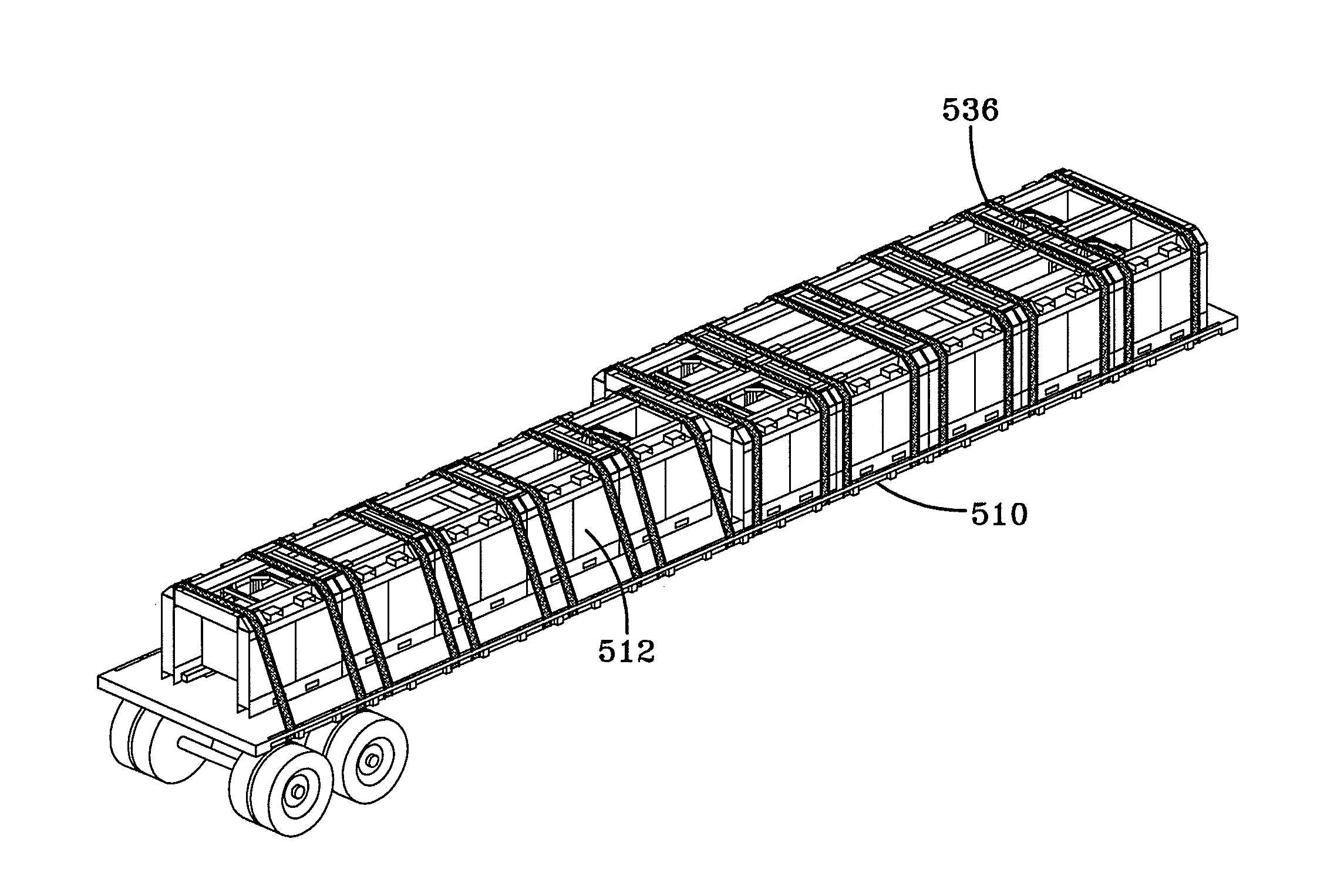
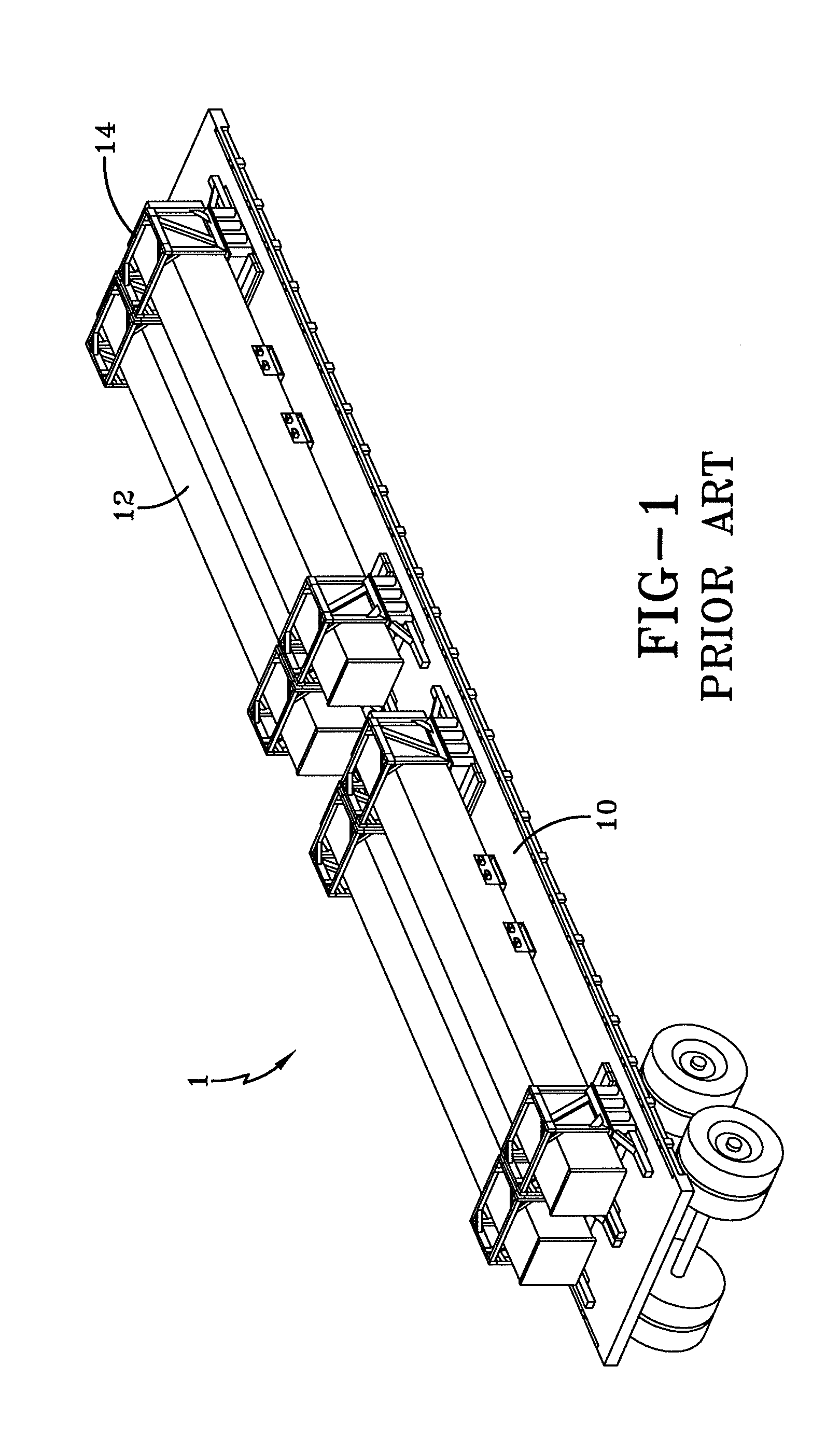
One known disadvantage in certain conventional armored applications is the allowable road weight that limits the numbers of encased missiles from being transported together.
Nevertheless, the combined weight of the truck and the missiles being transported which comprise the respective load cannot exceed 80,000 pounds.
Another disadvantage with conventional armor systems in the case of armor systems employed as protection for vehicles is that the excessive weight of the armor systems can tend to render the vehicles relatively immobile, or at least significantly slower.
This in turn can tend to cause the vehicles to be more vulnerable to attacks by high velocity and high caliber projectiles, and more significantly more vulnerable to attack, and even more significantly more vulnerable to repeated attacks by projectiles or fragments of projectiles.
In such applications, it is typically not possible for the armor or armor systems to be temporarily applied but rather are aspects of the structure.
In this regard, the armor systems could be difficult to replace in the event of damage or failure.
For example, at impact, the projectile can be blunted or otherwise damaged by the conventional ceramic-faced armor system.
At the same time, cracking or other damage to the conventional ceramic-faced armor system is inevitable which leads to a weakening of the integrity of the conventional ceramic-faced armor system and thus more vulnerable to future attacks.
Therefore, an additional protective structure cannot be employed and the missiles must be transported in a vulnerable manner as shown in FIG. 1.
Typical armored vehicles and body armor known in the art can be disadvantageous in that they fail to meet the requirements for protecting against, even low-caliber ammunition and / or are too heavy for normal use on streets in a city environment.
On the other hand, armored vehicles known in the art that may sufficiently protect against even low-caliber threats tend to be too heavy or cumbersome for use on roads and highways and can be too expensive to manufacture.

Method used


Image

  • Lightweight enhanced ballistic armor system
  • Lightweight enhanced ballistic armor system
  • Lightweight enhanced ballistic armor system

Examples


example

[0118]An example of the formulation in accordance with the present invention can be as follows. It should be appreciated that the formation of the present invention is not limited to this example, but would envisions any alternatives or modifications that would be understood by one skilled in the art. A polyurethane that is made by the reaction of a multifunctional amine and a multifunctional isocyanate without the addition of a solvent is provided. More specifically, an oligomeric ether or ester with diamine functionality reacted with a diisocyanate is provided.

[0119]As discussed above, alternatively the bundle or layered composite configuration may be environmentally protected by pressing or wrapping protective layers of polypropylene or other comparable materials, such as metal, Kevlar, S-glass, and the like, around the bundle or layered composite configuration. Edges may be reinforced with glass epoxy composites or other comparable protective and / or reinforcement materials as sh...

examples

Ballistic Testing

[0133]The Ballistic Barrier Test was conducted in order to test ballistic armored panels in accordance with the present invention.

STANAG 4241-50 Caliber Bullet Impact Test

[0134]The objective of the test was to impact each candidate plate in a specified quadrant with a volley of three 50-caliber armor-piercing (AP) projectiles, fired at 100+ / −8 msec intervals from .50 caliber Mann barrel devices. The projectiles were required to have velocities of 2788+ / −66 ft. / sec. These projectiles were to impact the specified plate quadrant within a 2-in circle, without key-holing or overlapping.

Test Item Configuration

[0135]The overall general test configuration is shown in FIG. 15 and is discussed in greater detail below.

[0136]The instrumentation setup was as shown in FIG. 16. A total of four Phantom cameras were used, and are described in Table 1 below.

TABLE 1BULLET IMPACT TEST CAMERA SPECIFICATIONSFrameExposureCameraTypeRateResolutionTimePurposeAPhantom 7105,0001280 × 308 20Pro...


PUM

PropertyMeasurementUnit
Lengthaaaaaaaaaa
Fractionaaaaaaaaaa
Thicknessaaaaaaaaaa

Abstract

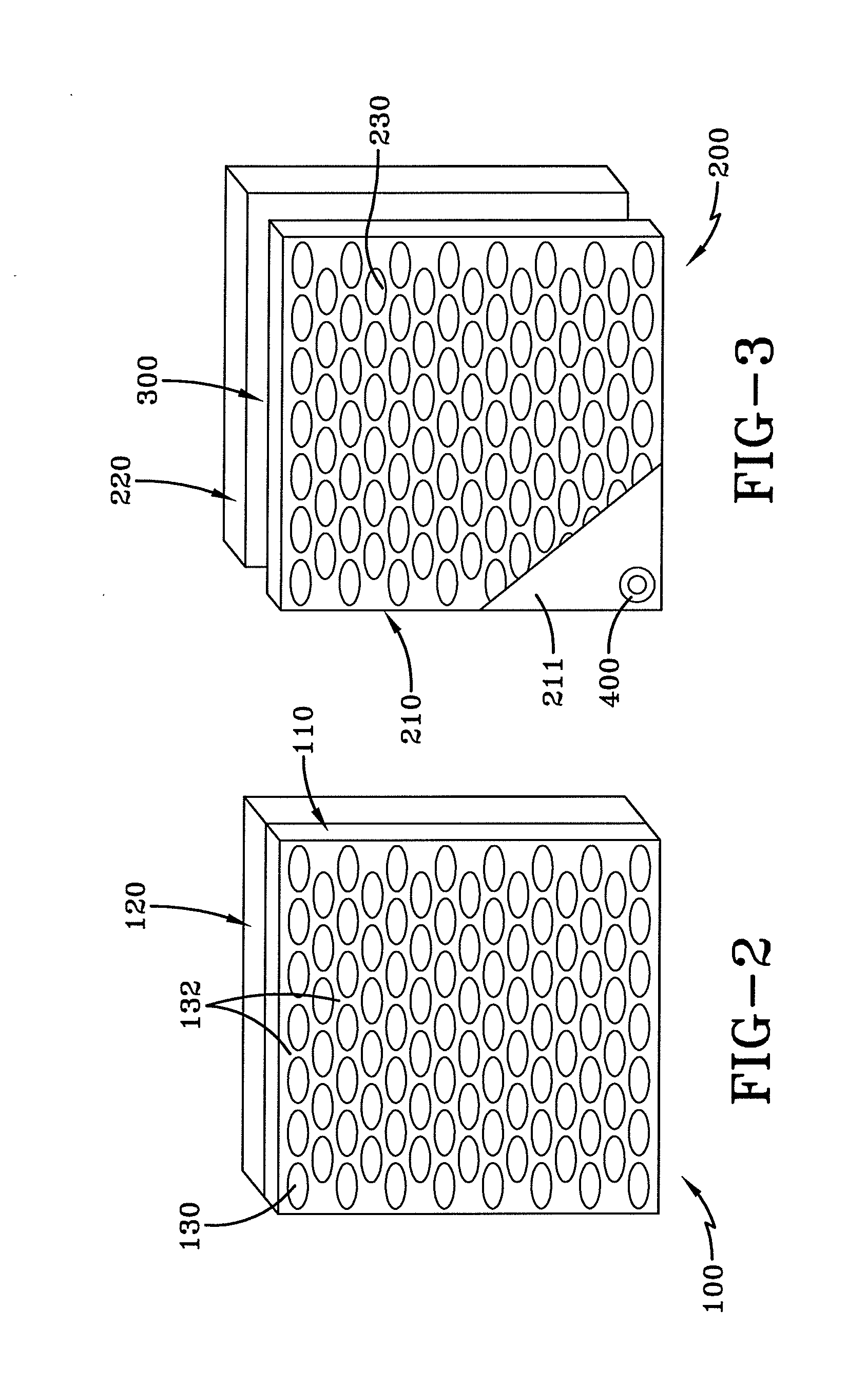
A lightweight ballistic armor system comprising at least one metal strike face plate, a laminate composite backing material secured to the at least one metal strike face plate and an optional air space provided between the metal strike face plate and the laminate composite backing material. The metal strike face plate or plates has a predetermined defined thickness and has a plurality of slotted holes set at an angle relative to the vertical orientation or axis of the metal strike face plate, or which are straight. The plurality of slotted holes is sufficiently small to prevent the passage of a projectile or fragment therethrough. The laminate composite backing material comprises at least one material selected from an aramid fiber material, S-glass, E-glass, polypropylene and UHMWPE, and is provided in combination with a polymer-based resin material. The optional air space provided between the metal strike face plate and the composite backing material has a depth in the range between 0-12 inches.

Description

CROSS-REFERENCE TO RELATED APPLICATIONS[0001]This application claims the benefit of U.S. Provisional Application Nos. 61 / 954,985 filed on Mar. 18, 2014 and 62 / 090,492 filed on Dec. 11, 2014, under Title 35, United States Code, Section 119(e). This application is also a continuation-in-part of U.S. application Ser. No. 14 / 006,065, filed on Sep. 18, 2013, which is a U.S. national phase application of and claims the benefit of International Application No. PCT / US2012 / 041642 filed Jun. 8, 2012, under Title 35, United States Code, Section 371, which claims the benefit of U.S. Provisional Application No. 61 / 520,320, filed Jun. 8, 2011, under Title 35, United States Code, Section 119(e), and U.S. Provisional Application No. 61 / 587,894, filed Jan. 18, 2012, under Title 35, United States Code, Section 119(e), the entire disclosures of all the foregoing are incorporated herein by reference in their entireties.STATEMENT OF GOVERNMENTAL SUPPORT[0002]The framework structure for a possible use of...

Claims


Application Information

Patent Timeline
IPC IPC(8): F41H5/04F41H7/04F41H1/00
CPCF41H5/0428F41H7/04F41H1/00F41H5/0421F41H5/0464F42B35/00
Inventor INGLEFIELD, CHARLES F.BARRY, BRIAN D.EILMANN, ROBERT W.GOOCH, WILLIAM A.
Owner AMERICAN TECHN COATINGS
Learn More