An apparatus for generating motion around a remote centre of motion

a remote centre of motion and apparatus technology, applied in the field of robots, can solve the problems of inability to exert large force on the body wall, physical constraints, and inability to accurately position at greater depth, so as to avoid use, avoid loss of accuracy or rcm stability, and facilitate manufacturing and control

Active Publication Date: 2015-12-10
KATHOLIEKE UNIV LEUVEN
View PDF1 Cites 52 Cited by
  • Summary
  • Abstract
  • Description
  • Claims
  • Application Information

AI Technical Summary

Benefits of technology

[0044]In one or more aspects, apparatuses of the present invention are easier to manufacture and control compared to other RCM mechanisms with distal actuation of the translational degree of freedom DOF3, requiring, thanks to the single sliding bar, mainly non-functional manufacturing tolerances and allowing embodiments where the translational degree of freedom DOF3 can be controlled by means of a combination only consisting out of rotary actuators mounted in direct drive to a concatenation of rigid linkages of the driving machine; thus avoiding the use of expensive or friction inducing zero-play rack and pinions or similar; not needing either the use of cable-based transmissions that could be installed to modify by means of a driving pulley rotary motion from a rotary actuator to a translational motion of sliding bar, but introduce compliance and load-depending displacement causing loss of accuracy or RCM stability; not needing the use of linear actuators to be mounted along the axis of the sliding bars either as such linear actuators would need to rotate along and add as such extra inertia to the pitch motion DOF and as such linear actuators are in general more costly and show lower performance than rotary actuators of a similar price class.
[0045]Compared to the prior art, in one or more aspects, apparatuses of the present invention can be made cheaper and easier to control as not needing to compensate for additional flexibility or play. Such system can be exploited ideally to remove surgical tremor and increase motion precision by programming various levels of damping, but can be equally designed to further reduce the mental workload of the surgeon and to provide additional safety measures by e.g. partial automation of the procedure or through introduction of shared control strategies.

Problems solved by technology

This makes accurate positioning more difficult at greater depth.
The incision points do not provide stable pivots either.
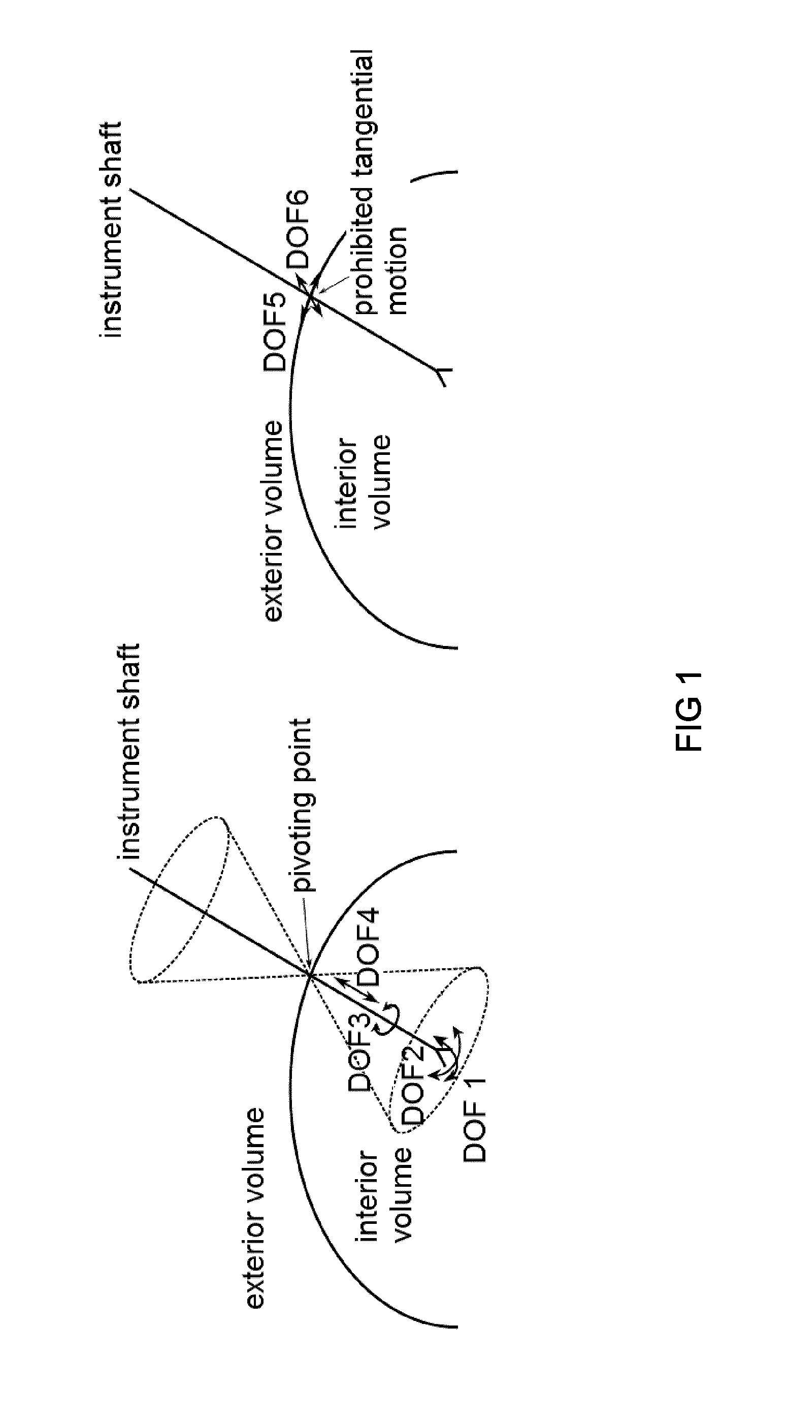
When the RCM is aligned properly with the entry port into the body, the instrument can only pivot around the RCM point and is thus physically constrained and not able to exert large forces upon the body wall.
Such virtual RCM systems can be bulky and need to be sufficiently powerful to ensure good dynamic behaviour at the instrument.
In case of failure it becomes difficult to guarantee patient safety, which makes them less suitable for MIS.
However, current mechanisms typically only support remote actuation of the distal two rotational degrees of freedom DOF1, DOF2.
Such translation / rotation stages not only take in a lot of space above the patient, blocking the access and view of the surgeon or visualisation devices; they also present a relatively large mass at the robot's end-effector limiting the dynamic range.
The stage and actuators form a variable load upon the lower elements of the kinematic chain; they jeopardize the achievable positioning accuracy, complicate the design of gravity compensation methods and further affect patient safety as actuators move in close vicinity to the patient.
With stages it also becomes more difficult to guarantee safety, maintain sterility and so on.
This can be achieved by employing two linear actuators that are controlled to move in a synchronous fashion at the cost of additional complexity, inertia and reduced reliability.
However, when the angle between the parallelogram's links becomes 90 degrees, this parallelogram might transform and shift towards an isosceles prism configuration, in which case the RCM is not maintained either.
Methods to circumvent this safety problem are complex, bulky and / or affect the achievable positioning precision of the mechanism.
If this is not the case the mobility of the mechanism can be completely lost and the parallelogram will be unable to extend or retract.
When adding play to the pivot points to relax these tight manufacturing constraints, the stability of the RCM point and the precision of instrument positioning suffers.
Such methods will introduce additional friction into the mechanism, typically limiting the smoothness of motion of the mechanism and will require a substantial torque / force to get the system running.
Depending on the friction it becomes difficult to allow small incremental motion.
Also, if at some point slip did occur it is not straightforward to detect and rectify this.
Zero-backlash versions require precise manufacturing, are costly and add substantial amounts of friction.
Secondly, the two pulleys must rotate at all times at exactly the same speed.
While the abovementioned approaches aim to avoid the loss of the RCM caused by a shift from the corresponding parallelogram to an isosceles trapezoid, they may at the same time further reduce the achievable workspace of the mechanism due to internal collisions between the additional plurality of links.
In fact the workspace by the proposed solution is somewhat restricted even without above corrective means.
Therefore the overall connection between local and remote site is rather bulky.
It becomes also difficult to realize longer distances between local and remote site as this requires the manufacturing of a pair of long, possibly complex, bars under tight manufacturing tolerances where small variations in manufacturing will cause the loss of mobility or might require introduction of play and subsequent loss of accuracy.
Again, imperfect synchronisation leads to loss of the RCM.
As described above, relying on high pre-tensioned belts is not reliable as correct synchronisation cannot be guaranteed and large amounts of friction are introduced.
In such case costly high-precision zero-play timing belt, pinions and high-precision zero-play rack and pinions need to be employed.
As a result the entire assembly becomes heavy and quickly cumbersome in assembly.
Also, the transmission from the local to the remote site of the mechanism further relies on four parallel bars that move relatively with respect to each other, this complicates the design of a compact end-effector that needs to accommodate for these four connecting bars.
In particular, the systems described above with remotely actuated translational degree of freedom DOF3 do possess a large range in the mechanism's roll angle of rotation DOF1, but only allow a limited working range in the pitch rotation angle DOF2 and require additional means to overcome straight angles where parallelograms might otherwise shift into isosceles trapezoid resulting in a loss of the RCM.

Method used


Image

  • An apparatus for generating motion around a remote centre of motion
  • An apparatus for generating motion around a remote centre of motion
  • An apparatus for generating motion around a remote centre of motion

Examples


Embodiment Construction

[0113]An important insight that lies at the basis of the proposed invention is that one single parallelogram and a means to position such parallelogram appropriately in space suffices to transfer motion from a local, or proximal, center of motion (which shall be referred to as LCM) to a remote center of motion (RCM). Depending on the mobility of the LCM, depending on the implementation of the single parallelogram and on the implementation of the means to position the single parallelogram appropriately in space, a mechanism can be composed that allows remote positioning of DOF1, DOF2 and DOF3. If additional means are foreseen to transfer the rotation degree of freedom DOF4, all available degrees of freedom DOF1, DOF2, DOF3 and DOF4 can be transferred to the remote instrument. Note that without loss of generality the rotation angles along DOF1, DOF2 and DOF4 will be respectively referred to as roll, pitch and yaw angle in the following.

[0114]It is a basic object of this document to di...


PUM


Abstract

Apparatus (10) for generating motion around a remote center of motion (RCM), comprising a distal link (L12, LR) arranged to revolve about the remote center of motion and to translate through the remote center of motion, a proximal link (L10, LI) arranged to revolve about a proximal center of motion (LCM), coupled to a base link, through a rotational joint (150) and a sliding joint (181), a first mechanism comprising a first link (L9, BE) pivotally coupled to the proximal link (L10) and to the distal link (L12) and operable to transfer motion of the proximal link relative to the proximal center of motion to a motion of the distal link relative to the remote center of motion by maintaining a parallelogram (PAR1), and a second mechanism operable to move the first link with two degrees of freedom in a plane parallel to the plane of motion of the proximal link, characterised in that the second mechanism comprises one link or a serial connection of links (L4, L8, L3, L7, L2, L6) connecting the base link to the first link, configured to have an orientation of instant motion which is different from an orientation of instant motion of the proximal link (L10), relative to the base link.

Description

TECHNICAL BACKGROUND[0001]The present invention is related to the field of robotics, in particular to the field of robot assisted surgery. The invention is particularly related to manipulators for minimal invasive surgery (MIS) where instruments are to operate precisely inside the human body while only being granted limited access through small entry incisions and where low volume occupancy above the operation table is considered highly desirable.[0002]In MIS, instruments can only reach the region of interest through the entry point into the body typically foreseen of a trocar. The trocar constraints the access to the region of interest, leaving only 4 degrees of freedom (DOF), compared to 6 DOF in open surgery, in the case rigid instruments are used. FIG. 1 shows the available degrees of freedom DOF1, DOF2, DOF3 and DOF4 consisting of three rotational DOFs (DOF1, DOF2 and DOF4) and one translational DOF (DOF3). The entry point is a pivotal point which causes motion reversal. The in...

Claims


Application Information

Patent Timeline
Patent Type & Authority Applications(United States)
IPC IPC(8): A61B19/00B25J9/10B25J18/00
CPCA61B19/2203B25J18/007A61B2019/2234A61B2019/265A61B2019/2215B25J9/1065A61B2034/302A61B2090/506A61B34/30A61B2034/305
Inventor VANDER POORTEN, EMMANUELGIJBELS, ANDYWOUTERS, NIELS
Owner KATHOLIEKE UNIV LEUVEN
Why Eureka
Try Eureka