Illuminating apparatus, vehicle headlamp and control system of vehicle headlamp

a technology of illumination apparatus and control system, which is applied in the direction of lighting and heating apparatus, fixed installation, instruments, etc., can solve the problems of inability to improve the safety of laser light, and the inability to see the information loaded in the illumination light. to achieve the effect of improving the visibility of information loaded in the illumination ligh

Active Publication Date: 2015-12-31
SHARP FUKUYAMA LASER CO LTD
View PDF11 Cites 69 Cited by
  • Summary
  • Abstract
  • Description
  • Claims
  • Application Information

AI Technical Summary

Benefits of technology

[0012]The disclosure is made considering the above problems, and it is desirable to provide an illuminating apparatus which is capable of improving the visibility of the information loaded on illumination light.

Problems solved by technology

However, in the related art, there is a problem related to visibility of the information loaded in the illumination light.
For example, in the technology disclosed in Japanese Unexamined Patent Application Publication No. 2013-103628, there is a problem in the safety of laser light in that a laser projector of a laser light scan type radiates collimated laser light to the road surface.
In addition, in the technology disclosed in Japanese Unexamined Patent Application Publication No. 2013-103628, visibility of the information loaded in the illumination light is not improved because output of laser light is difficult to be raised and brightened by regulation thereof.
In addition, in the technology disclosed in Japanese Unexamined Patent Application Publication No. 2014-49369, since a projection region of the visible light and a projection region of the infrared light coincide with each other, there is a problem regarding visibility of the infrared light as information loaded in the visible light.

Method used


Image

  • Illuminating apparatus, vehicle headlamp and control system of vehicle headlamp
  • Illuminating apparatus, vehicle headlamp and control system of vehicle headlamp
  • Illuminating apparatus, vehicle headlamp and control system of vehicle headlamp

Examples


first embodiment

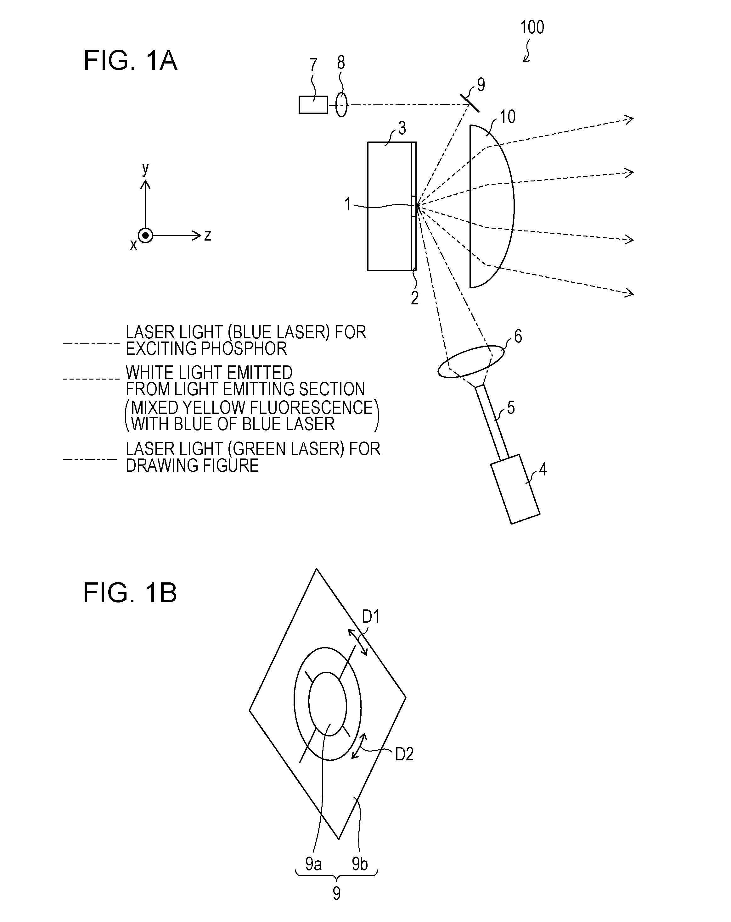
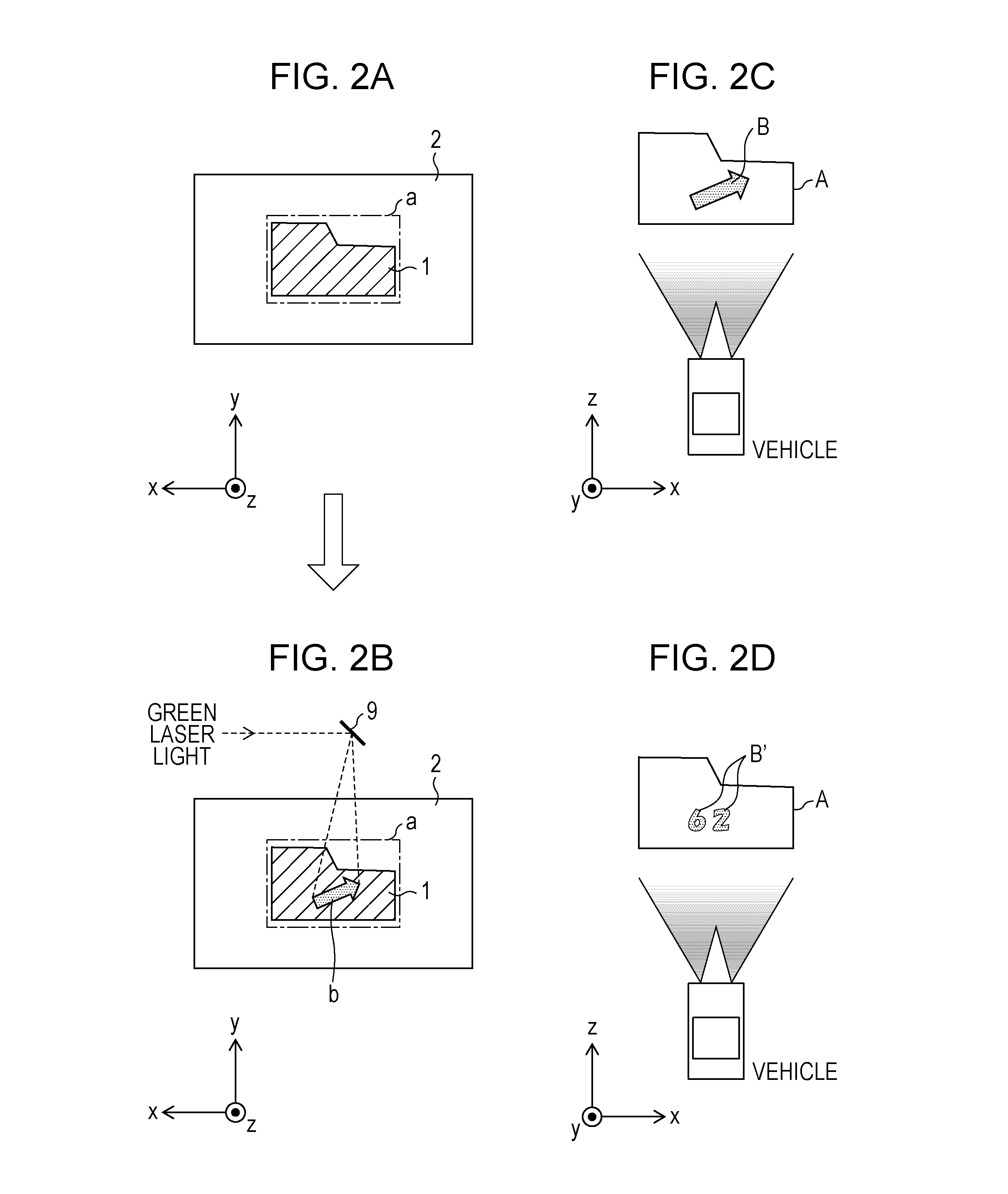
[0029]FIGS. 1A and 1B are views illustrating an illuminating apparatus 100 according to a first embodiment. FIG. 1A illustrates an outline configuration of the illuminating apparatus 100. The illuminating apparatus 100 has a configuration in which a surface on which excitation light to a light emitting section is irradiated coincides with a surface from which illumination light is mainly taken out, and hereinafter, the illuminating apparatus is referred to as a reflection type illuminating apparatus. A figure (arrow or number) is scanned and is drawn (communicates with a car navigation system or a speedometer described later) on a surface of the light emitting section 1 described later with green laser light. As illustrated in the drawing, the illuminating apparatus 100 includes a light emitting section 1, a light absorbing material 2, a support base 3, a first light source 4, a light guide member 5, an imaging lens 6, a second light source 7, a lens 8, a biaxial MEMS scanner (the l...

second embodiment

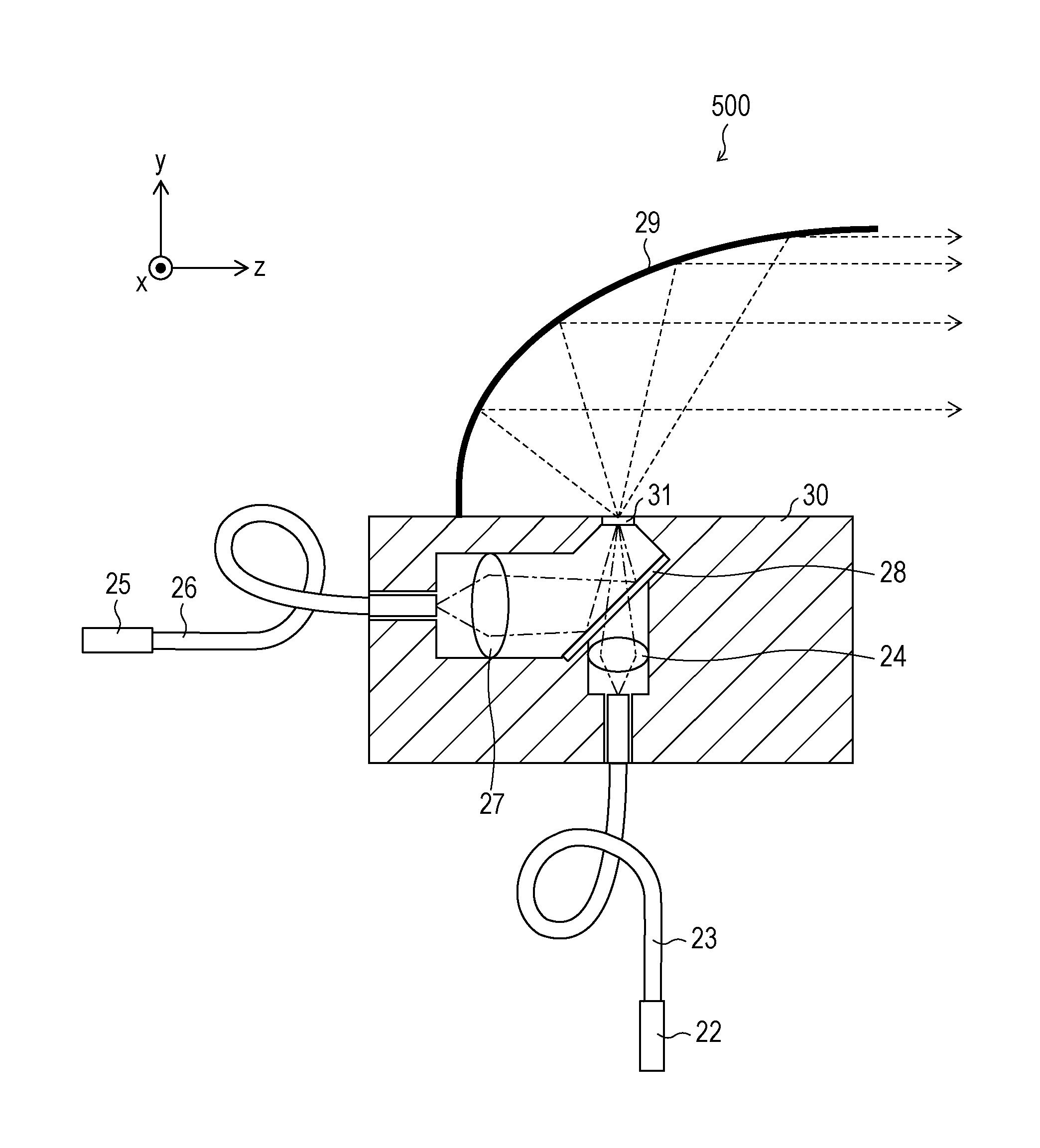
[0057]FIG. 3 is a view illustrating an outline configuration of the illuminating apparatus 200 according to the second embodiment of the disclosure. The illuminating apparatus 200 has a configuration in which a surface to which the excitation light is radiated with respect to the light emitting section and a surface from which the illumination light is mainly taken out face each other, and hereinafter, it is referred to as a transmission type illuminating apparatus. A beam spot of the red laser light on the surface of the light emitting section 1 is enlarged and projected (communicated with a vehicle camera, or the like; refer to the eighth embodiment). As illustrated in the drawing, the illuminating apparatus 200 includes the light emitting section 1, the light absorbing material 2, a support base 3a, the first light source 4, the second light source 7, the lens 8, a transparent member 11, an optical fiber 12, and a reflecting mirror (light radiating section) 13.

Light Emitting Sect...

third embodiment

[0075]FIG. 5 is a view illustrating an outline configuration of an illuminating apparatus 300 according to the third embodiment of the disclosure. The illuminating apparatus 300 beam-enlarges a line on a surface of the phosphor part 14 of a white LED with the green laser light and projects the resultant (frequently, attracting attention to the pedestrian). As illustrated in the drawing, the illuminating apparatus 300 includes a light emitting section 1a, the support base 3b, the second light source 7, the lens 8, the convex lens (light projection section) 10, and the reflecting mirror (the light radiating section) 13.

Light Emitting Section 1a

[0076]The light emitting section 1a is the white LED (Light Emitting Device) in which the yellow phosphor (YAG phosphor) is formed on a blue light emitting LED, and is configured to have a phosphor part (light emitting section) 14 and an LED chip (first light source) 15. The LED chip 15 outputs blue light that excites a phosphor contained in th...


PUM


Abstract

An illuminating apparatus includes a first light source that emits blue laser light, a light emitting section that emits light by being irradiated with the blue laser light, a second light source that emits green laser light, a biaxial MEMS scanner that irradiates a part of the light emitting section with the green laser light, and a convex lens that projects the light emitted from the light emitting section to the outside.

Description

BACKGROUND[0001]1. Field[0002]The present disclosure relates to an illuminating apparatus that projects light emitted from a light emitting section to the outside, a vehicle headlamp including the illuminating apparatus, and a control system for controlling the vehicle headlamp.[0003]2. Description of the Related Art[0004]Recently, after an illuminating lamp which simply radiates only white light, an illumination lamp has been developed in which illumination light has a function of transferring information or displaying information, for example, loading information in illumination light, or changing a color of the entirety or a part of a projection pattern of the illumination light. Particularly, it is considered that loading some information in the illumination light is an industrially matter as an added value in the illumination. In addition, in the case of a vehicle headlamp, it can contribute to safety of a vehicle and a pedestrian by reducing the likelihood of an accident at ni...

Claims


Application Information

Patent Timeline
Patent Type & Authority Applications(United States)
IPC IPC(8): B60Q1/08F21V8/00B60Q1/076F21S8/10
CPCG02B6/0068B60Q2400/50B60Q2300/45F21S41/14F21S41/16F21S41/24F21S41/25F21S41/675F21S41/141F21S41/151F21S41/176G02B6/0008
Inventor TAKAHASHI, KOJI
Owner SHARP FUKUYAMA LASER CO LTD
Why Eureka
Try Eureka