Fan disc

a technology of fan discs and fan plates, applied in the field of fan discs, can solve the problems of high restoring force, large overhung fan mass, and high vibration frequency of first order, and achieve the effects of enhancing torque transfer, high temperature capability, and enhancing torque transfer

Inactive Publication Date: 2015-12-31
ROLLS ROYCE PLC
View PDF4 Cites 16 Cited by
  • Summary
  • Abstract
  • Description
  • Claims
  • Application Information

AI Technical Summary

Benefits of technology

[0021]The connector may be a splined connector for engaging, in use, with a correspondingly splined connector portion of the drive shaft. Another option, however, is for the connector to be a flange bolted connector for engaging, in use, with a corresponding flanged portion of the drive shaft. According to this option, the flange bolted connector and corresponding flanged portion may have teeth which interlock across the flange joint to enhance torque transfer, e.g. in the form of a curvic or Hirth coupling. Additionally or alternatively, the connector and the drive shaft may have interconnecting locating spigot surfaces to enhance torque transfer between the connector and the shaft.
[0022]The stiffening ring may be formed of composite material. For example, it may be formed of a metal matrix composite material, such as titanium alloy metal matrix composite or aluminium alloy metal matrix composite. Another option is to form it of a fibre-reinforced polymer composite. Titanium alloy metal matrix composite, in particular, has a relatively high temperature capability. Such composites can combine high stiffness with high specific stiffness.
[0023]The disc body typically has dovetail root fingers at an outer side thereof which define flanks of axially extending slots. The stiffening ring may then project radially outwardly beyond the outermost surfaces of the dovetail root fingers. By extending radially outwardly further than conventional disc diaphragms, the torsional stiffness of the disc can be improved

Problems solved by technology

This results in a large overhung fan mass having a relatively low first order vibration frequency with large vibrational amplitudes and high restoring forces.
The already expensive fan disc forging is thus made even more expensive by its accommodation of a long and oversized rear drive arm 110.
However, in such spline drive fan discs, the support structure of the foremost bearing and the bearing envelope interferes with the space available for the conventional fan disc rear diaphragm.
Consequently, fan disc torsional stiffness is reduced, increasing the risk of coincidence of the 2D fan rotor frequency with an engine order forcing frequency.

Method used


Image

  • Fan disc
  • Fan disc
  • Fan disc

Examples


Embodiment Construction

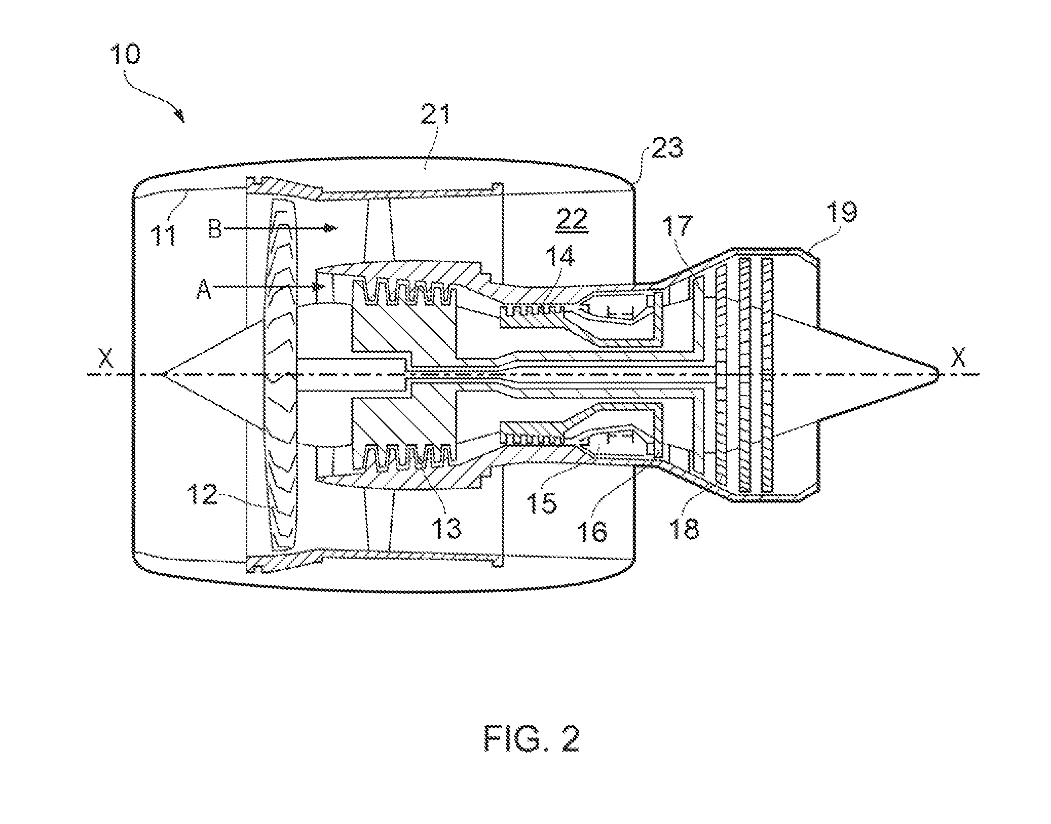
[0037]With reference to FIG. 2, a ducted fan gas turbine engine incorporating the invention is generally indicated at 10 and has a principal and rotational axis X-X. The engine comprises, in axial flow series, an air intake 11, a propulsive fan 12, an intermediate pressure compressor 13, a high-pressure compressor 14, combustion equipment 15, a high-pressure turbine 16, an intermediate pressure turbine 17, a low-pressure turbine 18 and a core engine exhaust nozzle 19. A nacelle 21 generally surrounds the engine 10 and defines the intake 11, a bypass duct 22 and a bypass exhaust nozzle 23.

[0038]During operation, air entering the intake 11 is accelerated by the fan 12 to produce two air flows: a first air flow A into the intermediate-pressure compressor 13 and a second air flow B which passes through the bypass duct 22 to provide propulsive thrust. The intermediate-pressure compressor 13 compresses the air flow A directed into it before delivering that air to the high-pressure compres...


PUM


Abstract

A fan disc is provided for supporting fan blades of a gas turbine engine. The fan disc has a disc body having axially extending slots for receiving, in use, dovetail root fixings of a circumferential row of fan blades. The fan disc further has an annular drive arm which extends radially inwardly from a forward portion of the disc body to a connector for engaging, in use, with a corresponding connector portion of a drive shaft of the engine. The fan disc further has a hoop stiffening ring which is removably mounted to a rear portion of the disc body, the stiffening ring being axially spaced from the drive arm to increase the torsional stiffness of the fan disc.

Description

FIELD OF THE INVENTION[0001]The present invention relates to a fan disc for supporting fan blades of a gas turbine engineBACKGROUND OF THE INVENTION[0002]FIG. 1 shows a conventional aero engine fan rotor and front bearing housing arrangement.[0003]A fan disc 100 supports a circumferential row of fan blades 102. The disc requires torsional stiffness to resist the 2D vibration mode of the fan rotor. This torsional stiffness is provided by front 104 and rear 106 axially spaced diaphragms which have differential hoop bending stiffnesses. An optional middle diaphragm 108 may be provided to produce a more even radial load distribution across the fan blade root fixings.[0004]The disc 100 has a rear drive arm 110 which extends to a bolted joint with the engine's fan shaft 112.[0005]A front bearing arrangement including a housing 114 and a front set of ball bearings 116 and a rear set of roller bearings (not shown), support and locate the fan shaft.[0006]The front set of bearings 116 is axia...

Claims


Application Information

Patent Timeline
Patent Type & Authority Applications(United States)
IPC IPC(8): F01D5/02F01D5/12F01D15/12F01D5/30
CPCF01D25/164F01D5/3007F01D5/025F05D2220/36
Inventor MAGUIRE, ALAN RUDALL, KENNETH FDOORBAR, PHILLIP J
Owner ROLLS ROYCE PLC
Why Eureka
Try Eureka