Buffering energy storage systems for reduced grid and vehicle battery stress for in-motion wireless power transfer systems

a technology of buffering energy storage and which is applied in the direction of capacitors, charging stations, transportation and packaging, etc., can solve the problems of increasing the stress on the power system transformer as well as the power line, adding a considerable fast transient load to the grid, and reducing the peak current of the in-motion wireless power transfer system. , to achieve the effect of prolonging the life of the in-motion wireless power transfer system and reducing the peak curren

Inactive Publication Date: 2016-01-07
UT BATTELLE LLC
View PDF2 Cites 56 Cited by
  • Summary
  • Abstract
  • Description
  • Claims
  • Application Information

AI Technical Summary

Benefits of technology

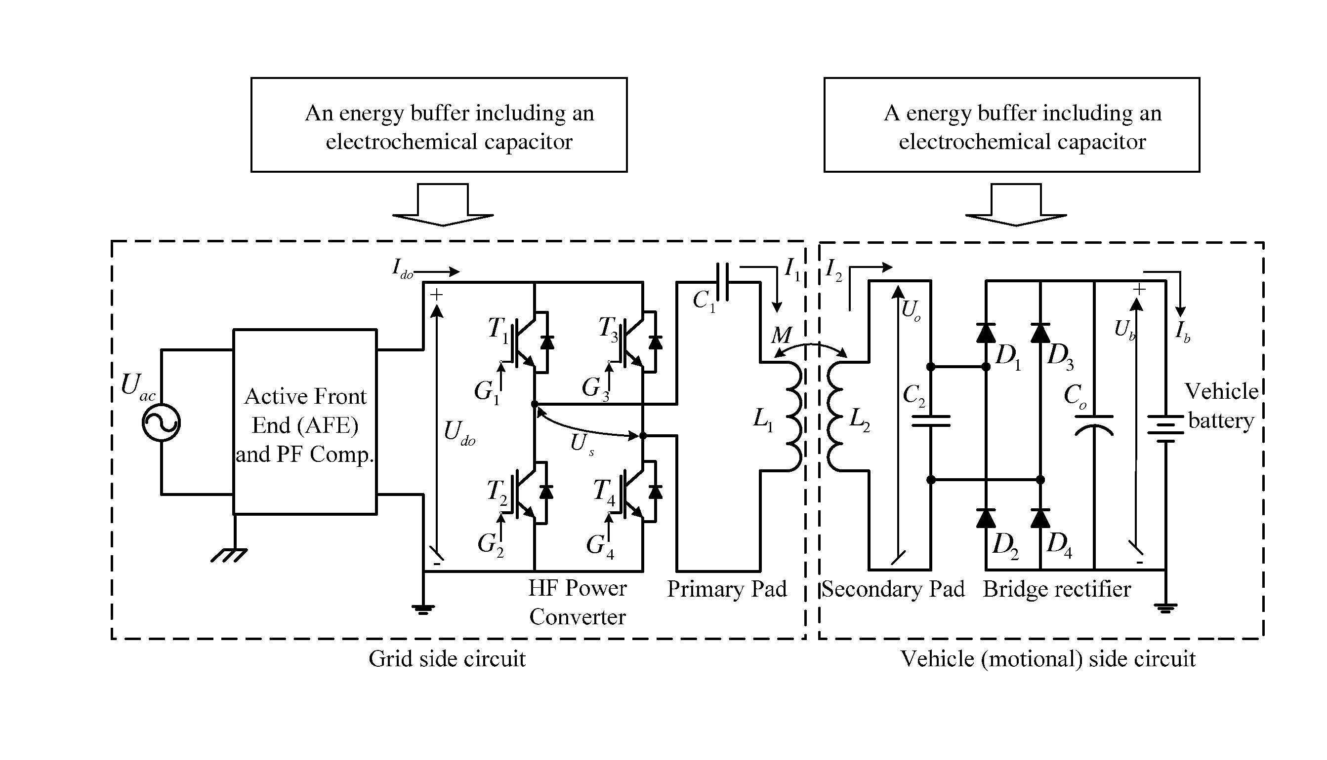
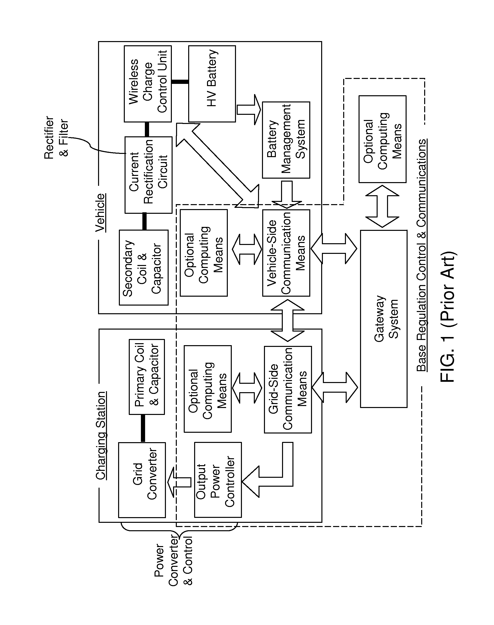
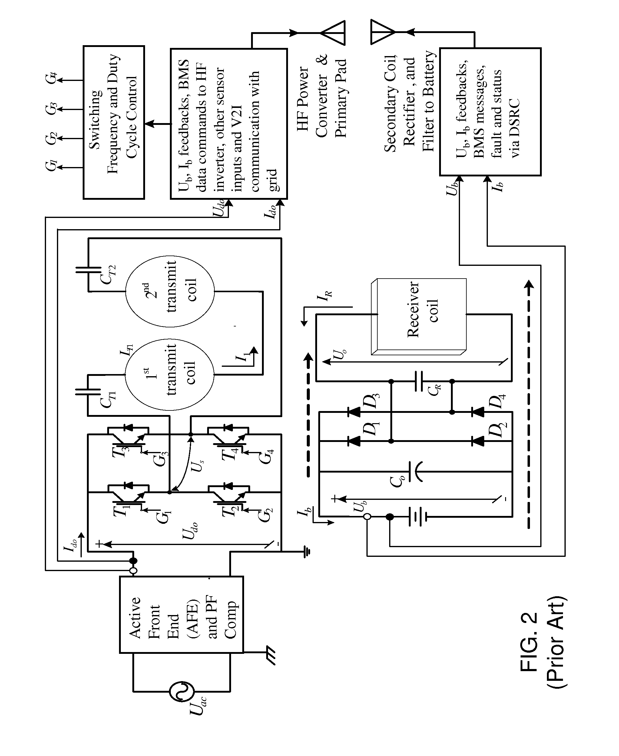
[0011]An energy buffer including an electrochemical capacitor can be added to the primary circuit and / or to the secondary circuit of in-motion wireless power transfer system. The energy buffer(s) can smooth the power delivered by the power grid and captured by a vehicle passing over an array of transmit coils through in-motion wireless power transfer. The reduction in the transient power transfer can reduce the peak current that flows through various components of the in-motion wireless power transfer system including a vehicle battery on the vehicle, and prolong the life of the in-motion wireless power transfer system.

Problems solved by technology

However, this high power transfer in a very short period of time adds a considerable fast transient loading to the grid.
In addition, the vehicle battery receives a pulse of high power in a very short period of time.
This fast transient on the grid current may trip the power system protection circuit and may add a burden on the power system transformers as well as the power lines.
On the battery side, this high current may cause a shortened battery lifetime since batteries are more likely to last longer if they are cycled with smooth currents free of any transients or high current peaks.

Method used


Image

  • Buffering energy storage systems for reduced grid and vehicle battery stress for in-motion wireless power transfer systems
  • Buffering energy storage systems for reduced grid and vehicle battery stress for in-motion wireless power transfer systems
  • Buffering energy storage systems for reduced grid and vehicle battery stress for in-motion wireless power transfer systems

Examples


example

[0080]Referring to FIGS. 13A and 13B, a laboratory setup of an in-motion wireless power transfer system is shown, which includes six transmit pads arranged such that neighboring transmit pads are spaced by an equal distance. An electric vehicle passing over the transmit pads is also shown. A transmitter circuit embodying the first exemplary transmitter circuit of FIGS. 5 and 5A were switchably installed into the primary circuit of the setup. A receiver circuit embodying the third exemplary receiver circuit of FIGS. 11 and 11A were switchably installed into the secondary circuit (receiver circuit) of the vehicle.

[0081]Referring to FIG. 14, a tabulated diagram illustrates relative positions of the receiver coil with respect to first two of the six transmit coils during the first nine positions at which measurements were taken. In this setup, each pad diameter is D, center to center spacing between the coils is L, and the pitch is D / L. With respect to these positions, primary and secon...


PUM


Abstract

An energy buffer including an electrochemical capacitor can be added to the primary circuit and/or to the secondary circuit of in-motion wireless power transfer system. The energy buffer(s) can smoothen the power delivered by the power grid and captured by a vehicle passing over an array of transmit coils through in-motion wireless power transfer. The reduction in the transient power transfer can reduce the peak current that flows through various components of the in-motion wireless power transfer system including a vehicle battery on the vehicle, and prolong the life of the in-motion wireless power transfer system.

Description

STATEMENT REGARDING FEDERALLY SPONSORED RESEARCH OR DEVELOPMENT[0001]This invention was made with government support under Contract No. DE-AC05-00OR22725 awarded by the U.S. Department of Energy. The government has certain rights in the invention.FIELD OF THE INVENTION[0002]The present invention relates to the field of wireless power transfer, and particularly to in-motion wireless power transfer systems for use in charging plug-in electric vehicles, and methods of operating the same.BACKGROUND OF THE INVENTION[0003]Plug-in Electric Vehicles (PEV) utilize a battery to store energy and power an electric motor to provide propulsion. When the battery becomes depleted, a PEV must be recharged for a period of time. Recharging may be performed by plugging the vehicle into an outlet or wirelessly with a primary and secondary coil. Wireless power transfer (WPT) charging has the benefit of being effortless and is the only option for in-motion vehicle charging.[0004]Examples of wireless power...

Claims


Application Information

Patent Timeline
Patent Type & Authority Applications(United States)
IPC IPC(8): B60L11/18H02J5/00
CPCH02J5/005B60L11/182B60L2210/10B60L2210/30B60L2210/40Y02T90/14Y04S10/126Y04S30/14Y02T10/7072B60L50/40B60L53/12B60L53/36B60L53/63B60L53/65H02J50/10H02J50/90B60L53/122H02J50/12H02J7/345Y02E60/00Y02T10/70Y02T10/72Y02T90/12Y02T90/167H02J50/40H02J50/005Y02T90/16
Inventor MILLER, JOHN M.ONAR, OMER C.
Owner UT BATTELLE LLC
Why Eureka
Try Eureka