Joined body and method for producing the same

a joint body and body technology, applied in the field of joint bodies, can solve the problems of low heat resistance, low oxidation resistance, low joint body strength, etc., and achieve the effect of easy reaction with a member

Active Publication Date: 2016-01-07
NGK INSULATORS LTD
View PDF4 Cites 17 Cited by
  • Summary
  • Abstract
  • Description
  • Claims
  • Application Information

AI Technical Summary

Benefits of technology

[0018]The present invention can more simply and more reliably join two members. The following is a plausible reason for this. For example, the joint is the oxide ceramic and is therefore stable at high temperatures and in oxygen atmospheres. Because the raw material of the joint is a relatively reactive metal raw material, the raw material can relatively easily react with a member, incorporate a component of the member, and allow the joint to be bonded to the member while the component is diffused ther

Problems solved by technology

However, because the joined bodies described in Patent Literature 1 and Patent Literature 2 have a metallic joining layer, the joined bodies have problems of low heat resistance, low oxidation resis

Method used


Image

  • Joined body and method for producing the same
  • Joined body and method for producing the same
  • Joined body and method for producing the same

Examples


experimental example 1

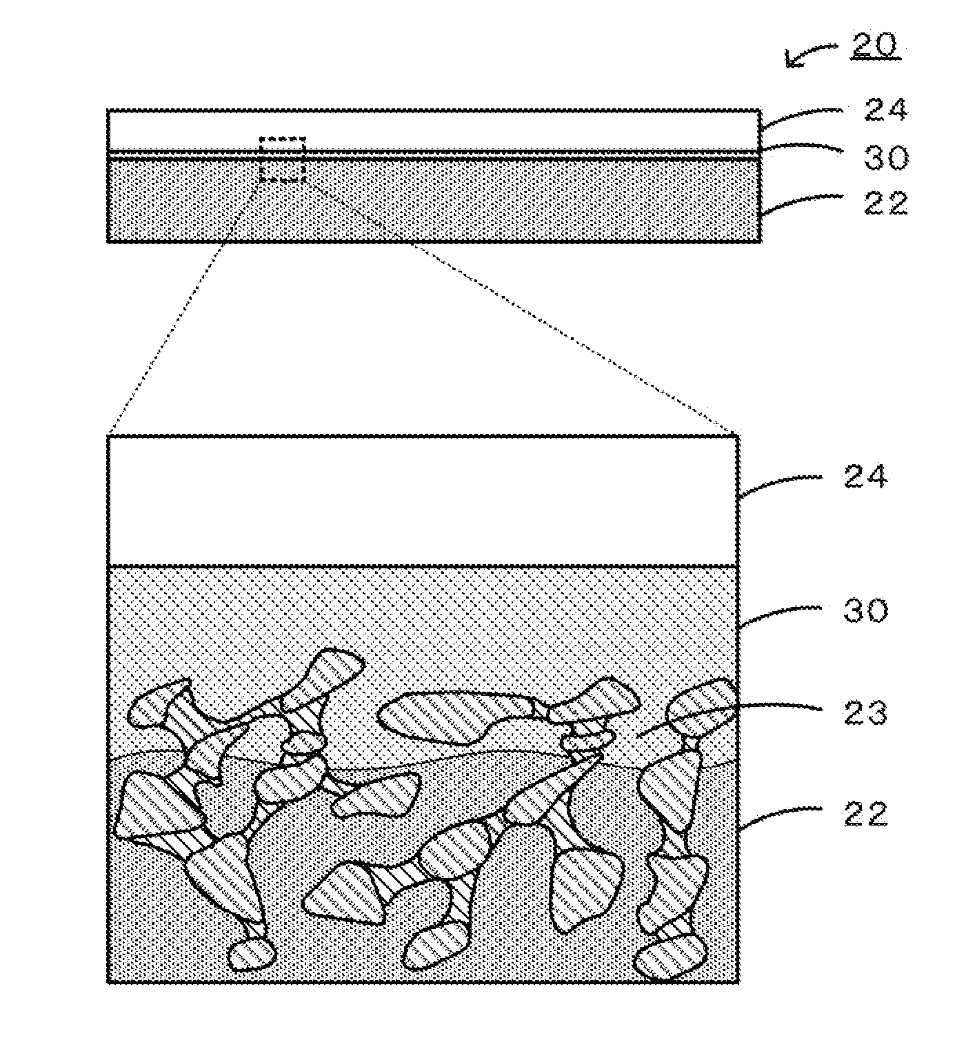
[0069]In Experimental Example 1, the first member and the second member were the Si-bonded SiC sintered bodies, and the metal raw material of the main oxide of the joint was an Fe powder. The raw materials of the joint were a first raw material powder (Fe powder) having an average particle size of 3 μm, which was smaller than the average pore size (10 μm) of the substrate, and a second raw material powder (Fe powder) having an average particle size of 35 μm, which was greater than the average pore size (10 μm) of the substrate. The first raw material powder and the second raw material powder were mixed at a volume ratio of 40:60. In Experimental Example 1, the joining condition was 750° C. for 1 hour in the air. Table 1 summarizes the members, the type of joint raw material, the blend ratio of metal raw materials, and the joining conditions for each sample of Experimental Examples 1 to 20.

experimental examples 2 to 7

[0070]In Experimental Examples 2 to 7, the addition of a second compound (conductive aid) containing a second component to the joint was examined. The second component was Ti, Sn, or Nb. In Experimental Examples 2 to 4, the metal raw material of the joint was the Fe powder, to which 1.0 mol %, 3.0 mol %, and 5.0 mol % TiO2 were added as the second compounds, respectively. Each of these additive amounts is the number of moles of the second compound based on the total number of moles with respect to the joint. In Experimental Examples 5 and 6, the metal raw material of the main component of the joint was the Fe powder, to which 1.0 mol % and 10 mol % SnO2 were added as the second compounds, respectively. In Experimental Example 7, the metal raw material of the main component of the joint was the Fe powder, to which 10 mol % Nb2O5 was added as the second compound.

experimental examples 8 to 11

[0071]Experimental Example 8 was produced in the same manner as Experimental Example 1 except that a raw material powder (Cu powder) having an average particle size of 3 μm was used alone. Experimental Example 9 was produced in the same manner as Experimental Example 8, except that the second component was Li, and 1 mol % Li2CO3 was added as the second compound. Experimental Example 10 was produced in the same manner as Experimental Example 1 except that a raw material powder (Ni powder) having an average particle size of 35 μm was used alone. Experimental Example 11 was produced in the same manner as Experimental Example 10 except that 1 mol % Li2CO3 was added as the second compound.


PUM

PropertyMeasurementUnit
Temperatureaaaaaaaaaa
Thicknessaaaaaaaaaa

Abstract

A joined body 20 according to the present invention includes a first member 22 made of a porous ceramic, a second member 24 made of a metal, and a joint 30 formed of an oxide ceramic of a transition metal, the joint 30 joining the first member 22 to the second member 24. Alternatively, a joined body may include a first member made of a dense material, a second member made of a dense material, and a joint formed of an oxide ceramic of a transition metal, the joint joining the first member to the second member.

Description

BACKGROUND OF THE INVENTION[0001]1. Field of the Invention[0002]The present invention relates to a joined body and a method for producing the joined body.[0003]2. Description of the Related Art[0004]A joined body that includes a pair of electrodes, which are formed of a metal layer, on a surface of a porous ceramic honeycomb body is proposed (see, for example, Patent Literature 1). In this joined body, the metal layers contain Cr and Fe, and a diffusion layer formed of a metal silicide is disposed within a boundary between the honeycomb body and the metal layers and ensures reliability of an electrical junction in high-temperature environments. A joined body that includes a ceramic member and a metal member joined together with a buffer layer is proposed (see, for example, Patent Literature 2). The ceramic member is a silicon nitride sintered body. The buffer layer in the joined body includes a silicon nitride sintered body layer containing 5% to 20% by mass of active metal nitride,...

Claims


Application Information

Patent Timeline
IPC IPC(8): C04B35/01C04B35/26C04B35/45
CPCC04B35/01C04B35/45C04B35/26C04B35/111C04B35/12C04B35/565C04B35/573C04B37/003C04B37/005C04B37/006C04B37/023C04B37/025C04B2235/3227C04B2237/06C04B2237/123C04B2237/124C04B2237/34C04B2237/343C04B2237/365C04B38/0016C04B2237/597C04B2237/61B23K2103/02B23K2103/12B23K2103/26B23K2103/08B23K2103/14B23K2103/18B23K2103/52B23K2103/172C04B37/026B23K35/26B23K35/262B23K35/28B23K35/32B23K35/325C04B38/0074B23K20/16B23K20/22B32B3/12B32B7/04B32B9/005B32B15/04B32B2305/024
Inventor IZUMI, YUNIEKOBAYASHI, YOSHIMASAMORIMOTO, KENJIKAWASAKI, SHINJI
Owner NGK INSULATORS LTD
Why Eureka
Try Eureka