A cabled pipe rack

a cabled pipe and rack technology, applied in the field of cabled pipe racks, can solve the problems of wasting time and arguing, structural engineers are struggling with computer aided load analysis, and delay in project delivery and completion, so as to save time, money, and more benefits for the industry

Inactive Publication Date: 2016-01-14
GARCIA ROLANDO S
View PDF13 Cites 5 Cited by
  • Summary
  • Abstract
  • Description
  • Claims
  • Application Information

AI Technical Summary

Benefits of technology

The invention is a new type of pipe rack that uses tension cables to support lateral movement and eliminates clashing between pipes. It also reduces internal forces and achieves good erection quality. The invention solves technical issues that previously existed between engineering, construction, and quality control teams. Additionally, the invention uses a cut-off beam to achieve full stiffness at the joints of the beam and column, which eliminates bolts overstressing and allows for a simpler installation process. Overall, the invention saves time, money, and structural steel by providing a more efficient and effective way to design, fabricate, and erect pipe racks.

Problems solved by technology

These pitfalls contribute to delay project delivery and completion.
Common cause of delay during engineering phase is when there are clashing problems of pipes and transversal steel bracings.
On the other hand, structural engineers handling the structural analysis firmly insist that pipes to give way if clashing exist because bracing is a major structural element of the pipe rack necessary to maintain lateral stability of the structure which cannot easily be relocated nor be removed unless engineering calculations are satisfied.
If a conventional pipe rack does not have enough transversal bracings, structural engineers are struggling much on dealing with their computer aided load analysis in achieving the lateral stability of the rack within their allowable limit especially in cases where taller racks are to be erected at project locations of high winds and high seismic forces.
Solving tons of clashing issues and technical mismatch during detailed design phase for a particular refinery project is a typical major concern and remain a repeated headache in the industry because structural engineers and piping engineers cannot easily resolve clashing issues, much time are wasted in arguing at the workplace during engineering meetings and model reviews:
However, to achieve a full end-moment connection in steel construction, if has to be a full welded joint connection of an I-beam to the column which requires massive welding work activities at the project site during erection phase, but this method is heavily opposed by construction team due to lots of constructability issues and entails longer period of delivery.
By simply looking at the given details, it appears that assumptions made to load analysis, and erection requirements are not matching technically.
However, this condition again seemed to be frustrating for erection team to achieve because steel components cannot simply be erected if gap exist between joints because it would demand excessive application of tightening force to the bolts which in return becomes highly critical for the bolts of being over-stressed.
Cases of over-stressing of bolts and tightening failures are abundance already during erection period at the site and in most cases have caused already to delay erection time and some have resulted to minor accidents.
This inappropriate action among construction team is technically opposed and argued by engineering team as a critical deviation from design specification seriously considered by quality control team as poor quality practice of erecting structural steel leading to a conclusion of a non-conformance behavior by the construction team.
In return, construction team defended themselves by pointing back to engineering team as the weakest team in the group by producing poor quality of design drawings that are difficult to construct at the project site resulting to a poor quality of erection.
These multi-level issues remain unsolved, a great challenge directed to the field of civil / structural engineering practice globally.

Method used


Image

  • A cabled pipe rack
  • A cabled pipe rack
  • A cabled pipe rack

Examples


Embodiment Construction

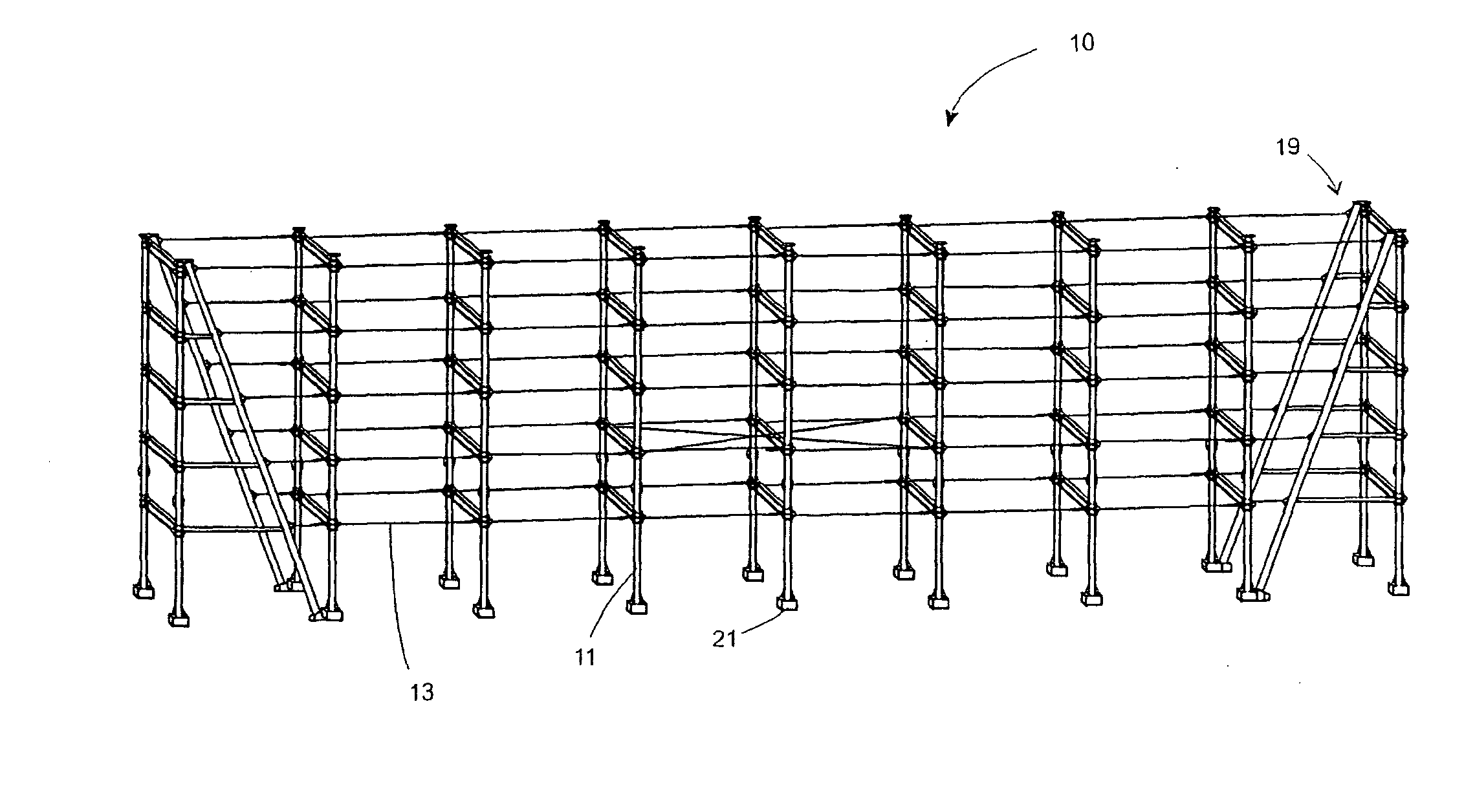
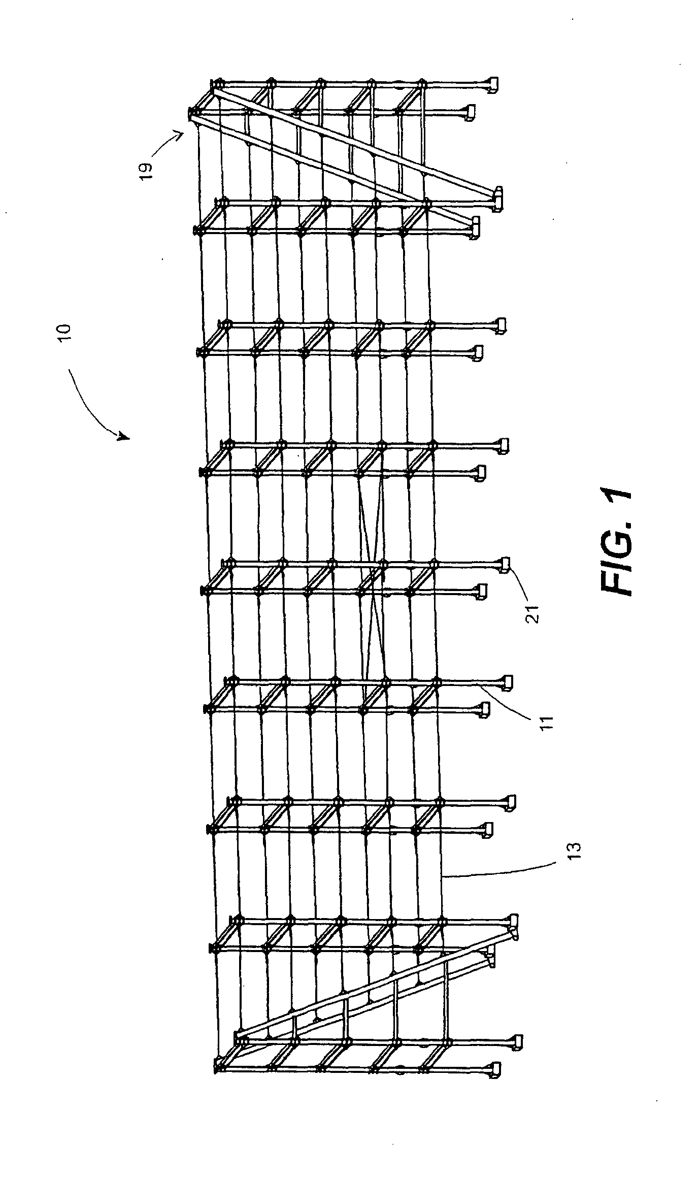
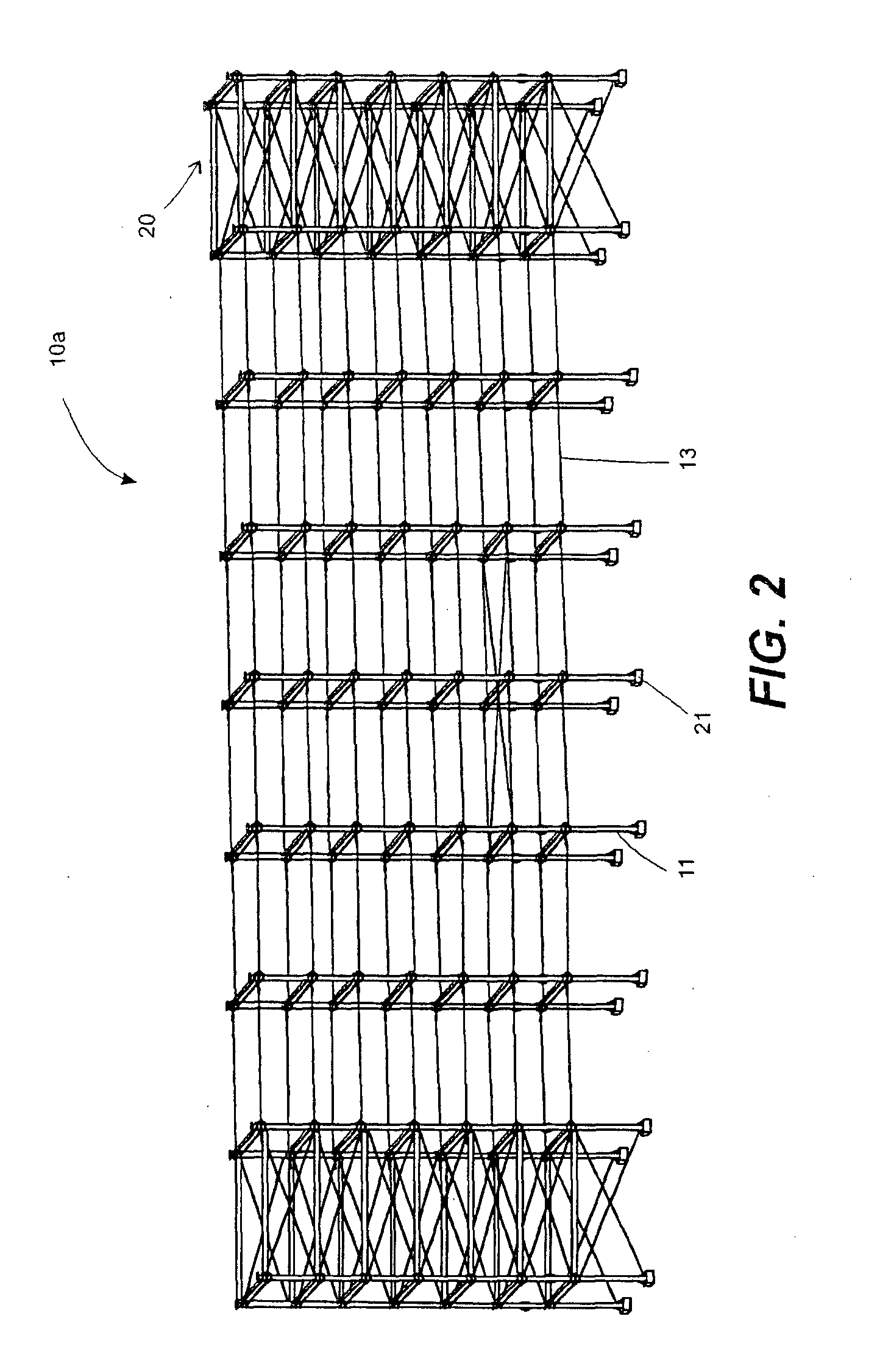
[0039]The invention is directed to rearranging things inside the box. A cabled pipe rack 10 and 10a as shown in FIGS. 1 & 2 will completely function similar to conventional pipe rack but largely of different structural composition, physical appearance and methods of creation.

[0040]The invention is an smart assembly of significant structural elements that have put together to form a robust structural framework simply made up of locally available construction materials, like: tubular hallow steel column 11 (circular, square, and rectangular section), a base plate 12 with a cut-off hole with same size and opening of hallow tubular column, a tension cable rod 13 with shackle 14 at one end and, turn buckle at the other end, an I-beam 15, steel bars 16, and a concrete-mixed material. The above composition of materials, the methods injected and collaborative functions of each element forming the structural system has come up to produce a more robust structural framework of pipe rack struct...


PUM

PropertyMeasurementUnit
lengthaaaaaaaaaa
lengthaaaaaaaaaa
distanceaaaaaaaaaa

Abstract

A cabled pipe rack is an assembly of structural elements put together to form a robust structural framework to function similar to conventional pipe rack. The invention employs tension cables to support lateral movements of transverse frames along the longitudinal direction. Tension cables are primarily anchored to the main anchoring structures strategically located at both ends of cabled pipe rack assembly. This structural assembly is a zero braced pipe rack completely eliminates pipe clashing issues to any bracing elements. This innovation have taken the structural benefits from a composite column made up of steel and concrete with a fully rigid connection at the base, and a fully welded joint connections of transverse beams and columns. The invention is a unique structural system seen as a suitable substitute to the conventional pipe rack.

Description

FIELD OF INVENTION[0001]This invention relates to a cabled pipe rack which is seen as a solution to resolve current issues surrounding the design, fabrication, and erection of a conventional pipe rack.BACKGROUND OF THE INVENTION[0002]Steel pipe rack structures are major items in the oil and gas industry, oil refinery, gas plant, liquefied natural gas plant, petrochemical plant, chemical plant, mining processing plant, and power plants. Steel pipe rack structure generally support pipes use to transfer or deliver any liquid, gas, and steam between equipments, storage tanks, utility areas, and flare lines, it also serve as support to power cables trays, instrument cable trays, light mechanical equipment, vessels, and valve access platforms.[0003]A conventional pipe rack is a structural steel framework mostly of multi-level in forms consisting series of transverse steel frames made up of steel H-section columns and transverse I-section beams that run along the length of the pipe system ...

Claims


Application Information

Patent Timeline
Patent Type & Authority Applications(United States)
IPC IPC(8): A47B55/04A47B47/02A47B55/02
CPCA47B55/04A47B55/02A47B47/027E04B1/185E04B1/30E21B19/15E04B2001/3583
Inventor GARCIA, ROLANDO, S.
Owner GARCIA ROLANDO S
Why Eureka
Try Eureka