
Package structure and fabrication method thereof

a technology of packaging structure and fabrication method, which is applied in the manufacture of printed circuits, printed circuit aspects, basic electric elements, etc., can solve the problems of difficult control of the size uneven height of copper pillars b>13/b>, and adversely affecting the product yield, so as to prevent bridging, improve product yield, and ensure reliable bonding

Inactive Publication Date: 2016-01-14
SILICONWARE PRECISION IND CO LTD
View PDF6 Cites 8 Cited by
  • Summary
  • Abstract
  • Description
  • Claims
  • Application Information

AI Technical Summary

Benefits of technology

The present invention provides a method for making a reliable electrical connection between a carrier and conductive elements by using a dielectric layer with conductive posts. The conductive posts are formed through through-holes in the dielectric layer, resulting in a uniform height and preventing bridging between them. This improves the stability of the connection and increases product yield.

Problems solved by technology

However, as the packages tend to have smaller sizes and fine pitches, solder bridging easily occurs between the solder balls, thus adversely affecting the product yield.
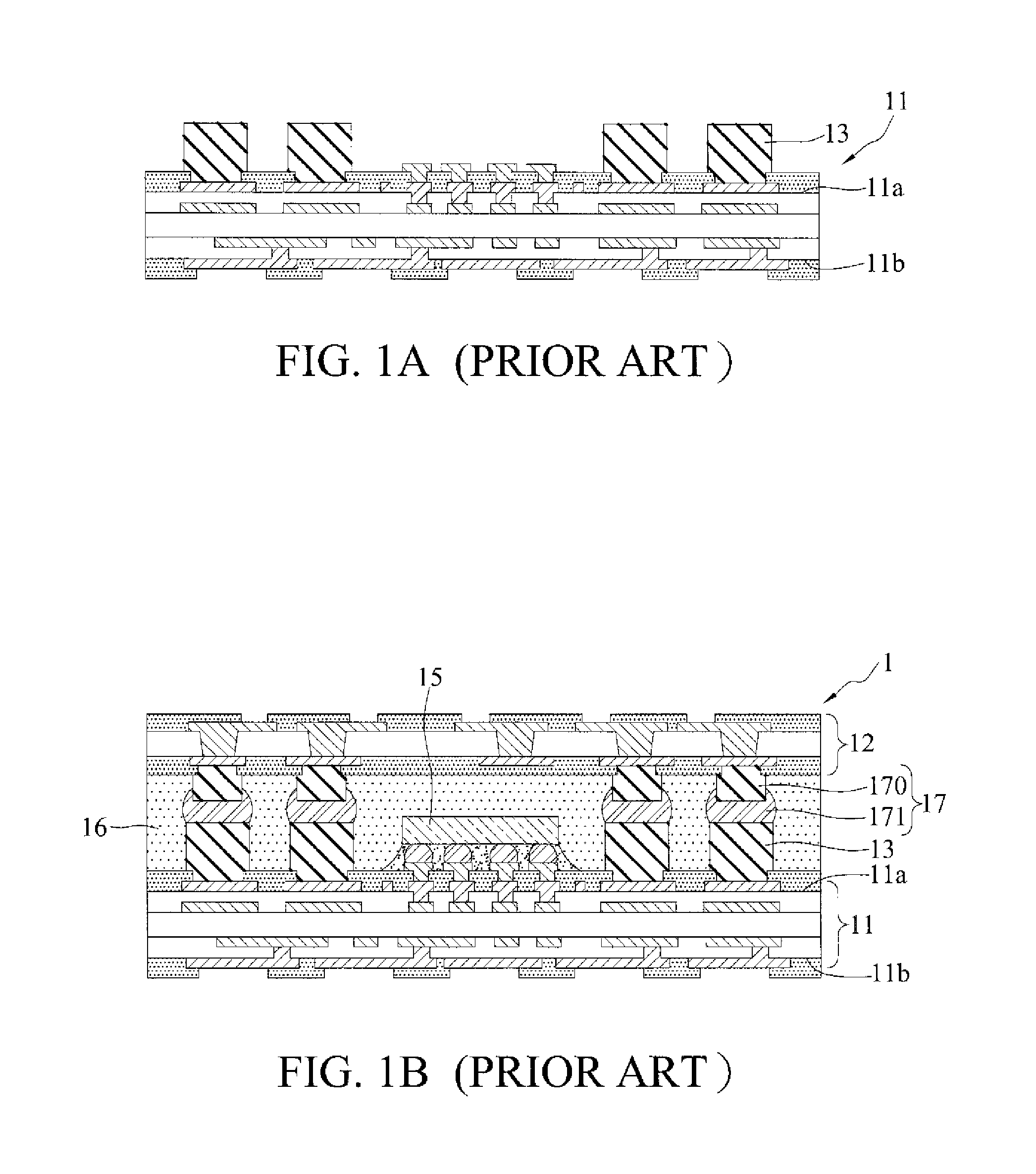
However, since the copper pillars 13 are formed by electroplating, the size of the copper pillars 13 is difficult to control and the copper pillars 13 tend to have uneven heights.
As such, a positional deviation easily occurs to the joints between the conductive elements 17 and the copper pillars 13 and hence a poor bonding easily occurs therebetween, thereby reducing the electrical performance and the product yield of the PoP structure 1.

Method used


Image

  • Package structure and fabrication method thereof
  • Package structure and fabrication method thereof
  • Package structure and fabrication method thereof

Examples


Embodiment Construction

[0024]The following illustrative embodiments are provided to illustrate the disclosure of the present invention, these and other advantages and effects can be apparent to those in the art after reading this specification.

[0025]It should be noted that all the drawings are not intended to limit the present invention. Various modifications and variations can be made without departing from the spirit of the present invention. Further, terms such as “first”, “second”, “on”, “a” etc. are merely for illustrative purposes and should not be construed to limit the scope of the present invention.

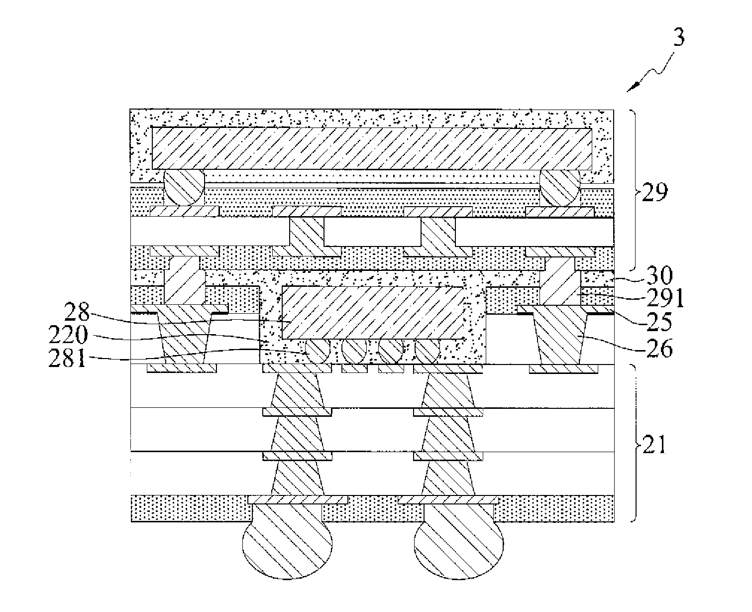
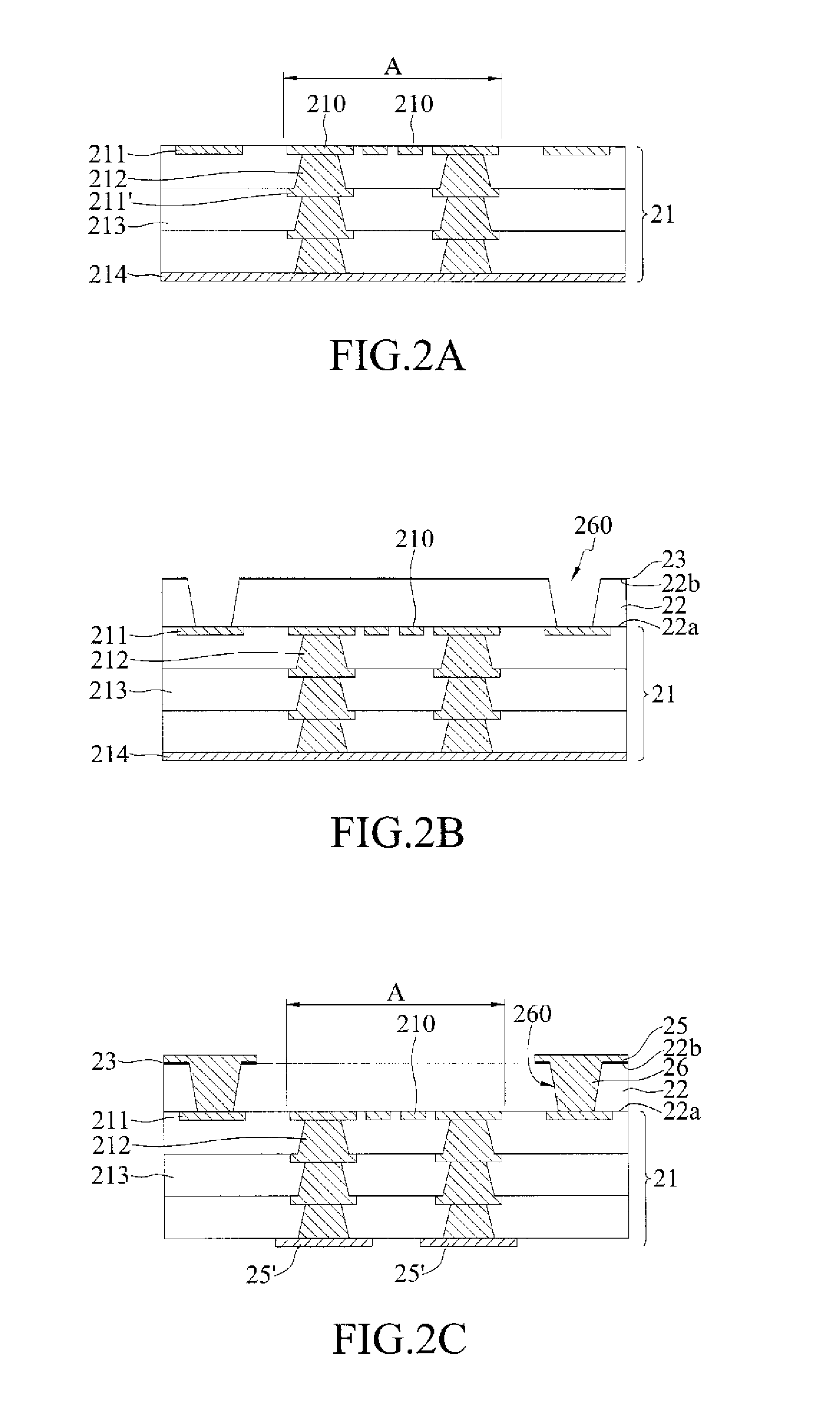
[0026]FIGS. 2A to 2G are schematic cross-sectional views showing a method for fabricating a package structure according to the present invention.

[0027]Referring to FIG. 2A, a carrier 21 having a plurality of first bonding pads 210 and a plurality of second bonding pads 211 is provided.

[0028]In the present embodiment, the carrier 21 is a packaging substrate, a semiconductor chip, a wafer, an interposer,...


PUM


Abstract

A method for fabricating a package structure is provided, which includes the steps of: providing a carrier having a plurality of bonding pads; laminating a dielectric layer on the carrier; forming a plurality of conductive posts in the dielectric layer; and forming a cavity in the dielectric layer to expose the bonding pads, wherein the conductive posts are positioned around a periphery of the cavity, thereby simplifying the fabrication process.

Description

BACKGROUND OF THE INVENTION[0001]1. Field of the Invention[0002]The present invention relates to package structures and fabrication methods thereof, and more particularly, to a package structure and a fabrication method thereof having simplified processes.[0003]2. Description of Related Art[0004]Along with the progress of semiconductor packaging technologies, various package types have been developed for semiconductor devices. To improve electrical performances and save spaces, a plurality of packages can be stacked to form a package on package (PoP) structure. Such a packaging method allows merging of heterogeneous technologies in a system-in-package (SiP) so as to systematically integrate a plurality of electronic elements having different functions, such as a memory, a CPU (Central Processing Unit), a GPU (Graphics Processing Unit), an image application processor and so on, and therefore is applicable to various thin type electronic products.[0005]Generally, to form a PoP structu...

Claims


Application Information

Patent Timeline
Patent Type & Authority Applications(United States)
IPC IPC(8): H01L23/498H01L21/48H01L23/00H01L25/00H01L25/065H05K1/11
CPCH01L23/49827H01L2224/16227H01L23/49822H01L24/17H01L24/81H01L25/50H01L25/0657H01L21/4857H01L21/486H05K1/111H01L2225/06517H01L2225/06513H01L2225/06548H01L2924/1517H01L2924/15153H01L23/49838H01L23/13H01L23/49811H01L23/5383H01L23/5389H01L2225/1088H01L24/16H01L2224/16237H01L2225/1023H01L2225/1058H01L2924/15311H01L2924/1533H05K3/4697H05K2201/10674H01L25/105
Inventor PAI, YU-CHENGLIN, CHUN-HSIENCHIU, SHIH-CHAOHSIAO, WEI-CHUNGSUN, MING-CHENSHEN, TZU-CHIEHCHEN, CHIA-CHENG
Owner SILICONWARE PRECISION IND CO LTD
Learn More