
Methods and systems for energy conversion and generation

a technology of energy conversion and energy generation, applied in the direction of electrochemical generators, liquid hydrocarbon mixture production, electrical apparatus, etc., can solve the problems of inability to meet the demand at any particular time, inability to readily store electricity, etc., and achieve the effect of improving efficiency and high efficiency

Active Publication Date: 2016-01-21
THERMOGAS DYNAMICS
View PDF6 Cites 32 Cited by
  • Summary
  • Abstract
  • Description
  • Claims
  • Application Information

AI Technical Summary

Benefits of technology

The present invention is about a method for generating electricity from non-fossil fuel energy sources such as wind, tidal energy, wave energy, hydro energy, geothermal energy, solar energy, and nuclear energy. The invention allows for the storage of electricity produced by generators that cannot vary generation of electricity on demand, which is often the case with renewable energy sources. The electricity can be used to electrolyse water, which can be done at high temperature and pressure. The invention also includes the option of further processing the methane to form hydrocarbons other than methane or hydrocarbon derivatives. The non-fossil fuel energy sources are preferred, especially renewables. The invention provides a way to efficiently generate electricity from these sources and utilize it for various applications.

Problems solved by technology

Electricity cannot be readily stored, but combustible fuel and oxygen can, albeit in liquid or solid form.
For example where wind energy is used to generate electricity to the grid, it cannot be relied upon to meet the demand at any particular time.

Method used


Image

  • Methods and systems for energy conversion and generation
  • Methods and systems for energy conversion and generation
  • Methods and systems for energy conversion and generation

Examples


Embodiment Construction

[0129]Embodiments of the present invention will now be described, by way of example only, with reference to the accompanying drawings in which:

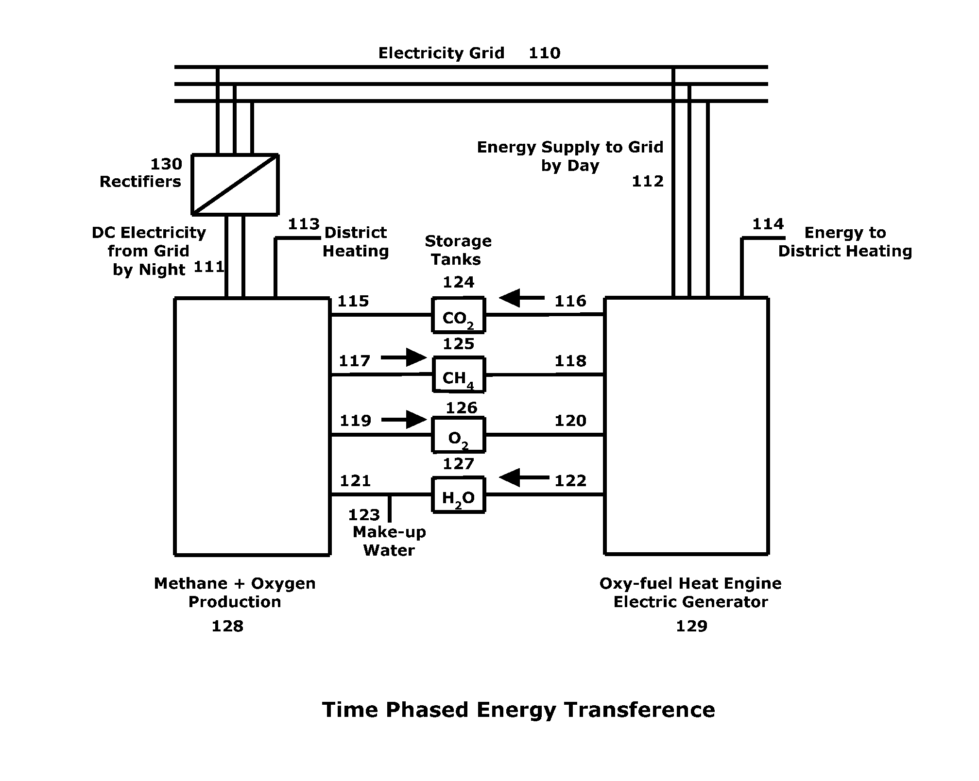
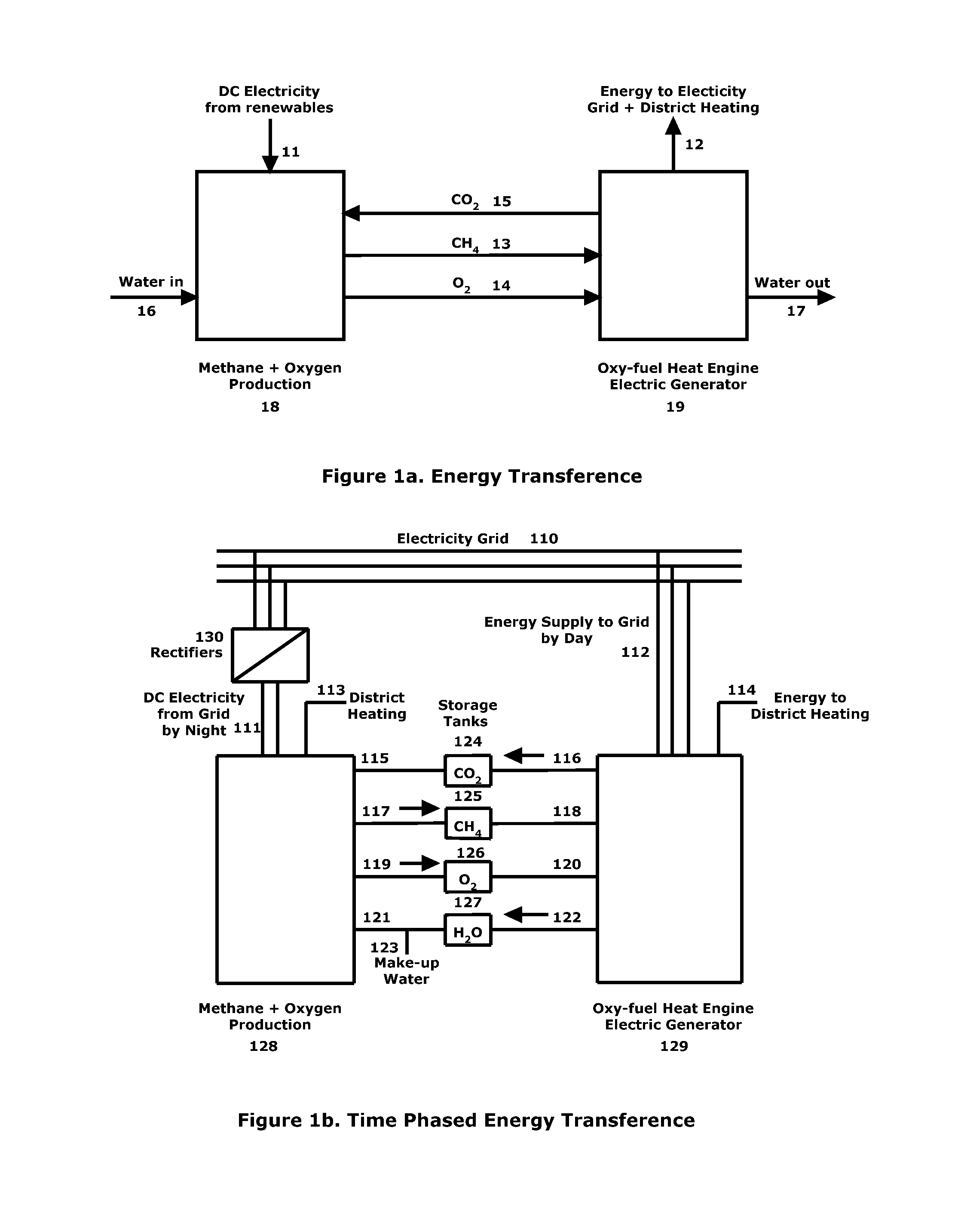
[0130]FIG. 1a shows a schematic diagram of energy transfer according to the present invention and FIG. 1b shows a particular embodiment of the invention in which time-phased energy transfer is conducted.

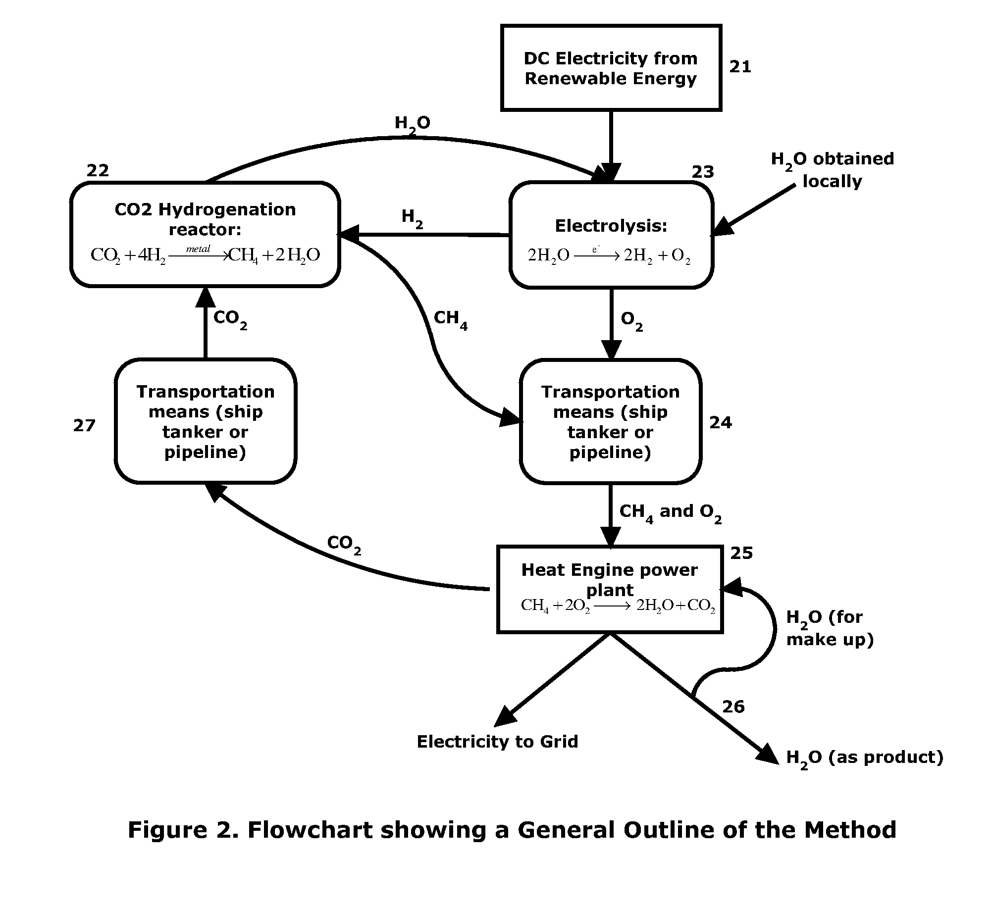
[0131]FIG. 2 shows a flow chart of one embodiment of the present invention.

[0132]FIG. 3a shows a schematic representation of an electrolysis chamber.

[0133]FIG. 3b shows a schematic representation of an apparatus for the hydrogenation of carbon dioxide.

[0134]FIG. 4a shows a schematic representation of inputs, take-offs and storage capabilities associated with the present invention.

[0135]FIG. 4b shows a pipe system according to the present invention for transporting products of the present invention.

[0136]FIG. 5 shows a schematic representation of a combined cycle oxy-fuel gas turbine generator with CO2 recovery.

[0137]FIG. 6 shows a combined 2-s...


PUM

PropertyMeasurementUnit
temperatureaaaaaaaaaa
temperaturesaaaaaaaaaa
temperatureaaaaaaaaaa

Abstract

The invention relates to methods and systems of converting electrical energy to chemical energy and optionally reconverting it to produce electricity as required. In preferred embodiments the source of electrical energy is at least partially from renewable source. The present invention allows for convenient energy conversion and generation without the atmospheric release of CO2. One method for producing methane comprises electrolysis of water to form hydrogen and oxygen, and using the hydrogen to hydrogenate carbon dioxide to form methane. It preferred to use the heat produced in the hydrogenation reaction to heat the water prior to electrolysis. The preferred electrical energy source for the electrolysis is a renewable energy source such as solar, wind, tidal, wave, hydro or geothermal energy. The method allows to store the energy gained at times of low demand in the form of methane which can be stored and used to generate more energy during times of high energy demand. A system comprising an electrolysis apparatus and a hydrogenation apparatus, and a pipeline for the transportation of two fluids, is also described.

Description

[0001]This present invention relates to improved methods and systems of converting electrical energy to chemical energy, and optionally converting the chemical energy back to electrical energy and thereby providing electrical energy when required. The present invention provides highly efficient methods and systems for making combustible fuel or petrochemical feed stock from electrical energy, wherein the electrical energy may, in certain embodiments, be provided by non-fossil fuel energy and associated technologies. In an alternative embodiments the present invention may be used for converting electrical energy to chemical energy at certain times (e.g. of relatively low demand or price), for subsequent conversion to electrical energy at other times (e.g. where demand or price is high). The present invention can involve a recurrent process of energy transference for use in the supply of emissions-free electricity, and optionally district heating and a source of water for drinking or ...

Claims


Application Information

Patent Timeline
Patent Type & Authority Applications(United States)
IPC IPC(8): F02C3/22C07C1/12C25B1/04C25B9/18C25B15/02H01M8/06
CPCF02C3/22C07C1/12C25B1/04C07C2523/46C25B15/02H01M8/0656C07C2521/04C25B9/18C10G2/50C10G50/00F01K13/00F01K19/00Y02E60/34B01D53/62Y02E60/36C25B11/00C07C9/04Y02P20/129Y02P20/133Y02P20/582Y02E20/16Y02E20/32Y02E20/34Y02E60/50C25B9/73C25B9/70
Inventor SIMPSON, ROBERT
Owner THERMOGAS DYNAMICS
Learn More