Transmission-type target for x-ray generating source, and x-ray generator and radiography system including transmission-type target
a technology of generating source and transmission type, which is applied in the field of transmission type target for x-ray generating source, and x-ray generator and radiography system including transmission type target, can solve the problems of excessive target temperature increase, thermal stress of target, melting, evaporation, etc., and achieve stable output of x-rays and high reliability
- Summary
- Abstract
- Description
- Claims
- Application Information
AI Technical Summary
Benefits of technology
Problems solved by technology
Method used
Image
Examples
exemplary embodiment 1
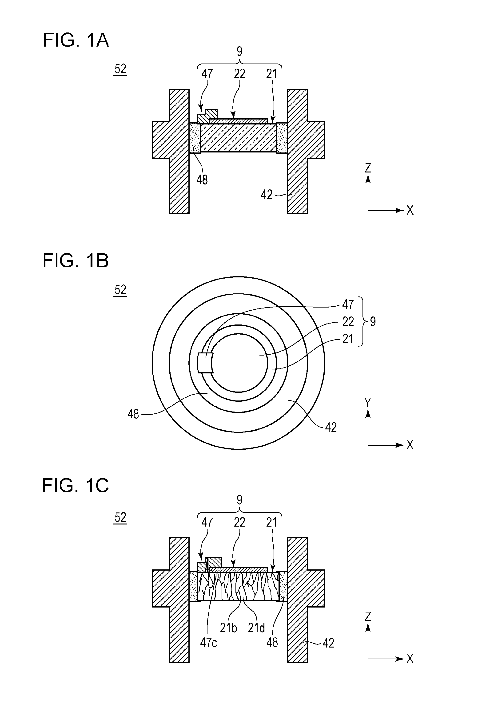
[0087]FIG. 1A illustrates a configuration of the target 9 produced in the present exemplary embodiment. First, two disk-shaped polycrystalline diamond members 117 each having a diameter of 5 mm and a thickness of 1 mm are prepared. The polycrystalline diamond members 117 are self-supported polycrystalline diamond produced by the CVD method. Next, residual organic compounds on the surface of each of the polycrystalline diamond members 117 are cleaned by a UV ozone ashing apparatus.
[0088]One of the polycrystalline diamond members 117 is polished, and a cross section that passes through the centers of the opposite surfaces of 5 mm in diameter is obtained by polishing. The obtained polished surface is cleaned by the UV ozone ashing apparatus, and the cleaned cross-sectional subject of the polycrystalline diamond member 117 is obtained.
[0089]This cross-sectional subject of the polycrystalline diamond member 117 is analyzed by the electron-beam backscattering diffraction method. The resul...
exemplary embodiment 2
[0100]Next, the polycrystalline diamond member 117 and the target 9 heated under a reducing atmosphere and a reduced-pressure atmosphere by substantially the same method as in exemplary embodiment 1 are prepared.
[0101]For the polycrystalline diamond member 117, a metal layer (not illustrated) made of tungsten and having a diameter of 3 mm and a layer thickness of 6 μm is formed on each of the opposite surfaces each having a diameter of 5 mm, as in the target layer 22 in exemplary embodiment 1, and a subject for electrical conductivity is produced. When the electrical conductivity is evaluated from the obtained electrical conductivity subject, it is 0.22 pSm−1 at a room temperature of 300 K. The electrical conductivity is measured with a combination of Impedance Analyzer 1260 and Dielectric Interface 1296 of Solartron.
[0102]Next, for the target 9, a metal layer (not illustrated) made of tungsten and having a diameter of 3 mm and a layer thickness of 6 μm is formed on a surface oppose...
exemplary embodiment 3
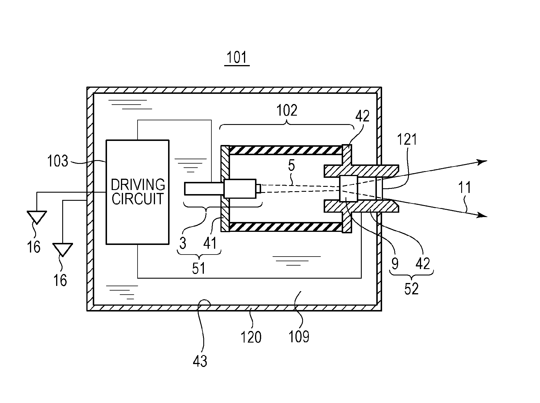
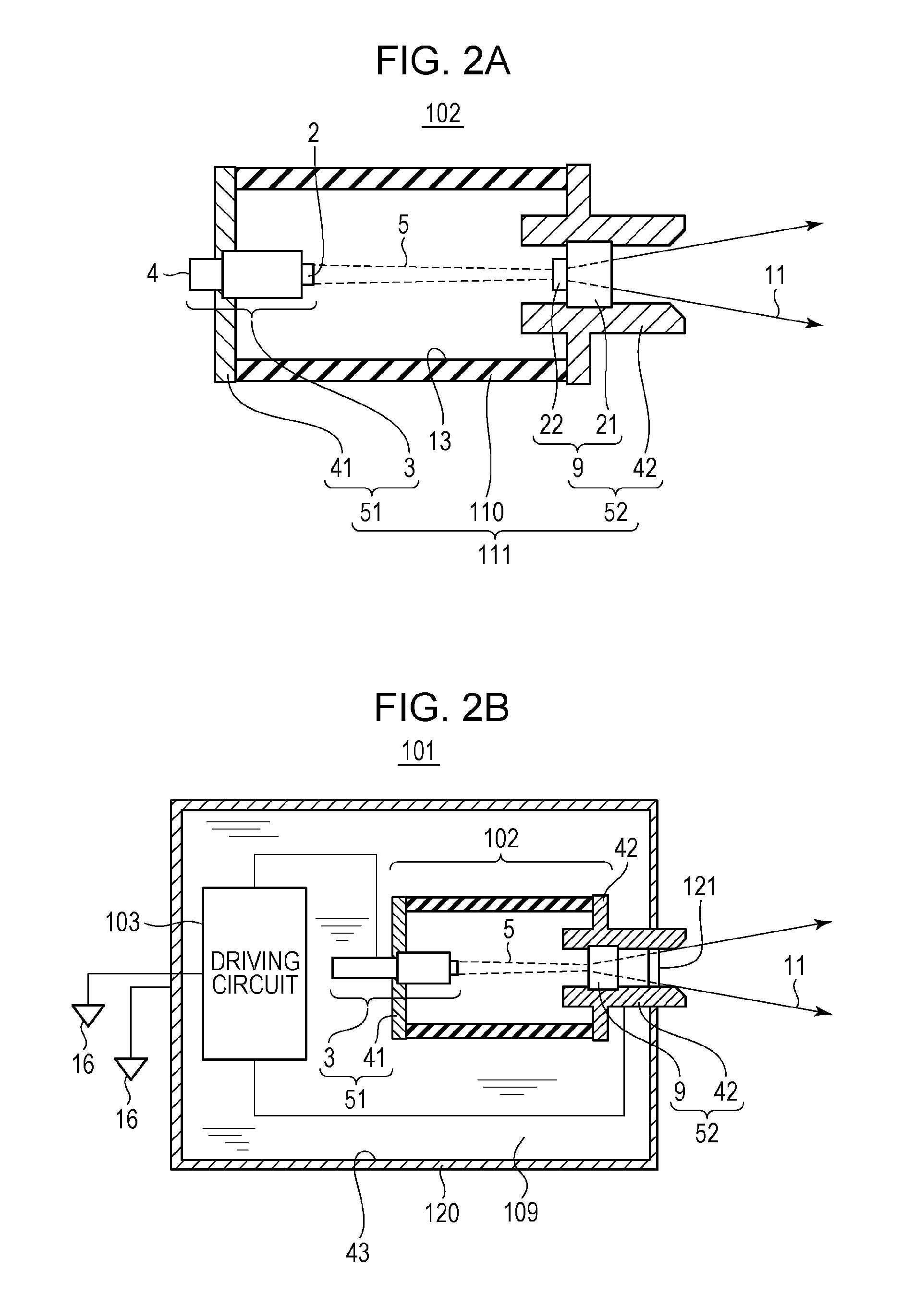
[0103]Next, an X-ray generator including the target of the present invention is produced by the process described below, the X-ray generator is made to operate, and the withstand discharge performance, the intensity of outputting X-rays, and the stability of the anode current are evaluated.
[0104]The target 9 illustrated in FIGS. 1A and 1B is produced by substantially the same method as in exemplary embodiment 1. Next, the connection electrode 47 is formed in a region between the peripheral edge of the target layer 22 and a side surface of the transmissive substrate 21, and the wax material 48 made of an alloy of tin and silver is arranged on the side surface of the transmissive substrate 21. In addition, the target 9 including the connection electrode 47 and the tubular anode member 42 are bonded together with the wax material 48, and the anode 52 is produced. The anode 52 is the one in which the peripheral edge of the target 9 and the tubular inner surface of the tubular anode memb...
PUM
 Abstract
Description
Claims
Application Information
 - R&D
- Intellectual Property
- Life Sciences
- Materials
- Tech Scout
- Unparalleled Data Quality
- Higher Quality Content
- 60% Fewer Hallucinations
Browse by: Latest US Patents, China's latest patents, Technical Efficacy Thesaurus, Application Domain, Technology Topic, Popular Technical Reports.
© 2025 PatSnap. All rights reserved.Legal|Privacy policy|Modern Slavery Act Transparency Statement|Sitemap|About US| Contact US: help@patsnap.com


