Concentrating photovoltaic skylight based on holograms and/or methods of making the same

a photovoltaic skylight and hologram technology, applied in photomechanical equipment, pv power plants, instruments, etc., can solve the problems of large-scale connectivity and cost concerns, system cumbersome integration into windows, and large number of c-si wafers tending to dominate the cost of the overall photovoltaic module, so as to reduce the quantity of costly, and reduce the quantity of expensive.

Inactive Publication Date: 2016-01-28
GUARDIAN GLASS LLC
View PDF2 Cites 9 Cited by
  • Summary
  • Abstract
  • Description
  • Claims
  • Application Information

AI Technical Summary

Benefits of technology

[0004]CPV systems typically use large area optical components to collect and direct sunlight, and transfer the energy onto small, high-efficiency photovoltaic (PV) cells. CPV systems have the potential for higher overall conversion efficiencies while reducing the quantity of costly, environmentally sensitive semiconductor materials, etc. Sunlight may in some instances be focused with concentration ratios of 100× to 1000×. Calculations suggest that a concentration ratio of approximately 10× should enable a photovoltaic system to be produced that uses at least 90% less silicon material.
[0005]To further improve efficiency, some CPV systems incorporate mechanic...

Problems solved by technology

The inclusion of the large number of c-Si wafers tends to dominate the cost of the overall photovoltaic module.
Unfortunately, however, integrating hundreds of PV cells all aligned to their respective optics frequently leads to large-scale connectivity and cost concerns.
Notwithstanding their obtrusive nature, these systems can be to...

Method used


Image

  • Concentrating photovoltaic skylight based on holograms and/or methods of making the same
  • Concentrating photovoltaic skylight based on holograms and/or methods of making the same
  • Concentrating photovoltaic skylight based on holograms and/or methods of making the same

Examples


Embodiment Construction

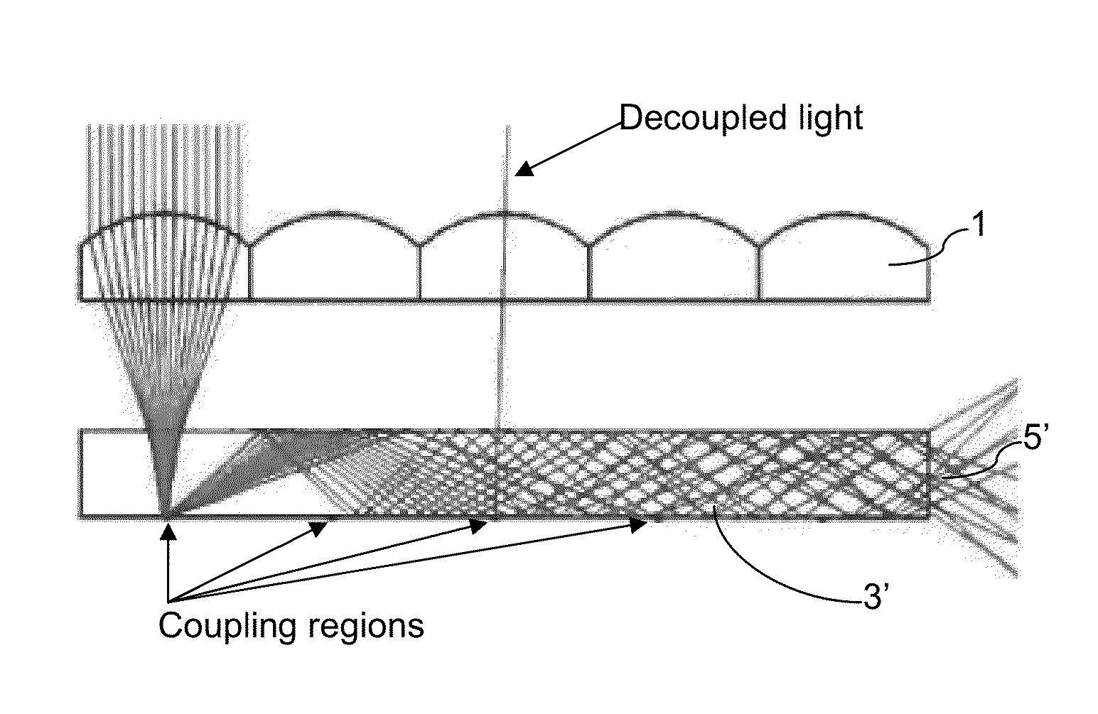
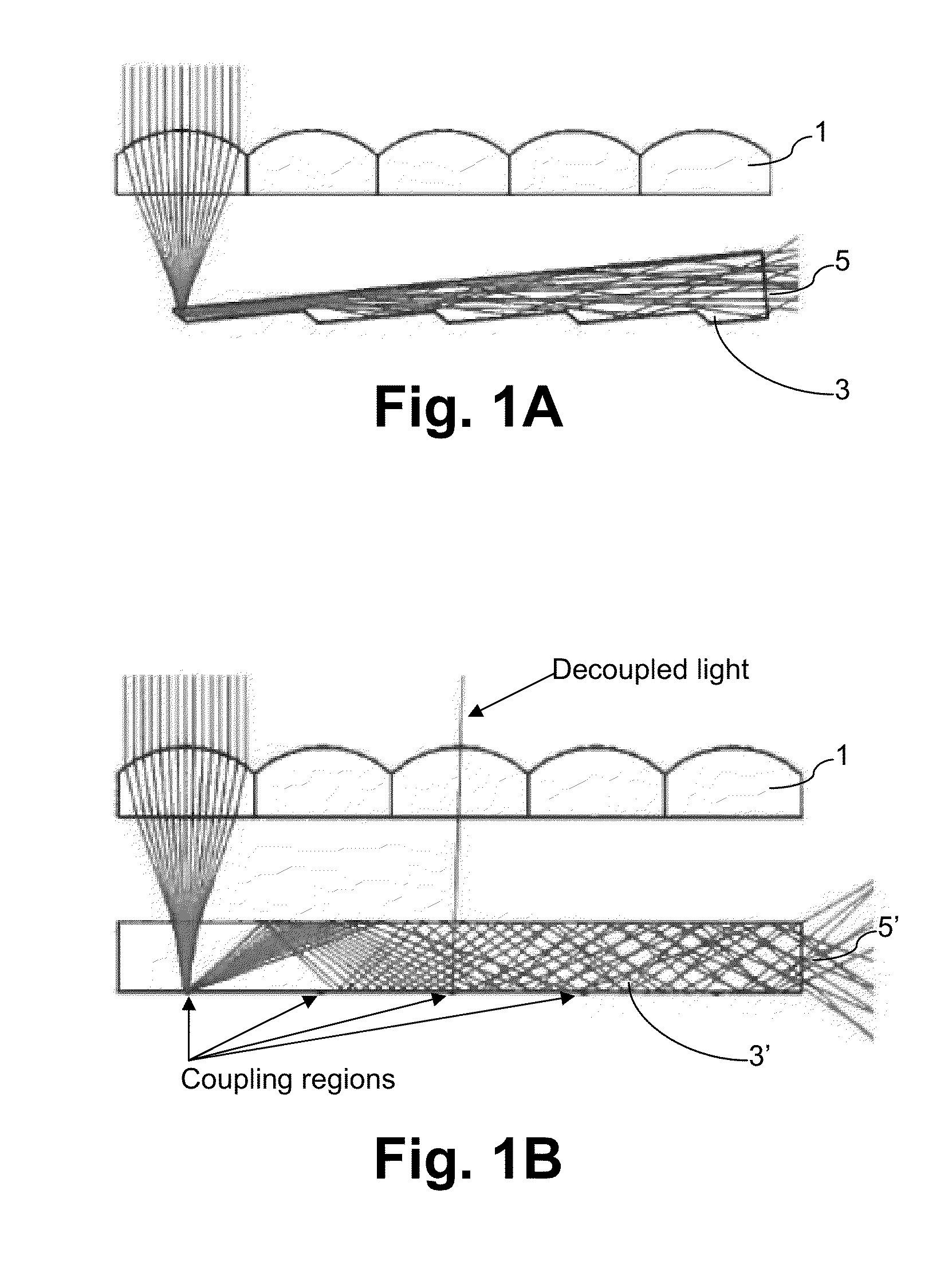
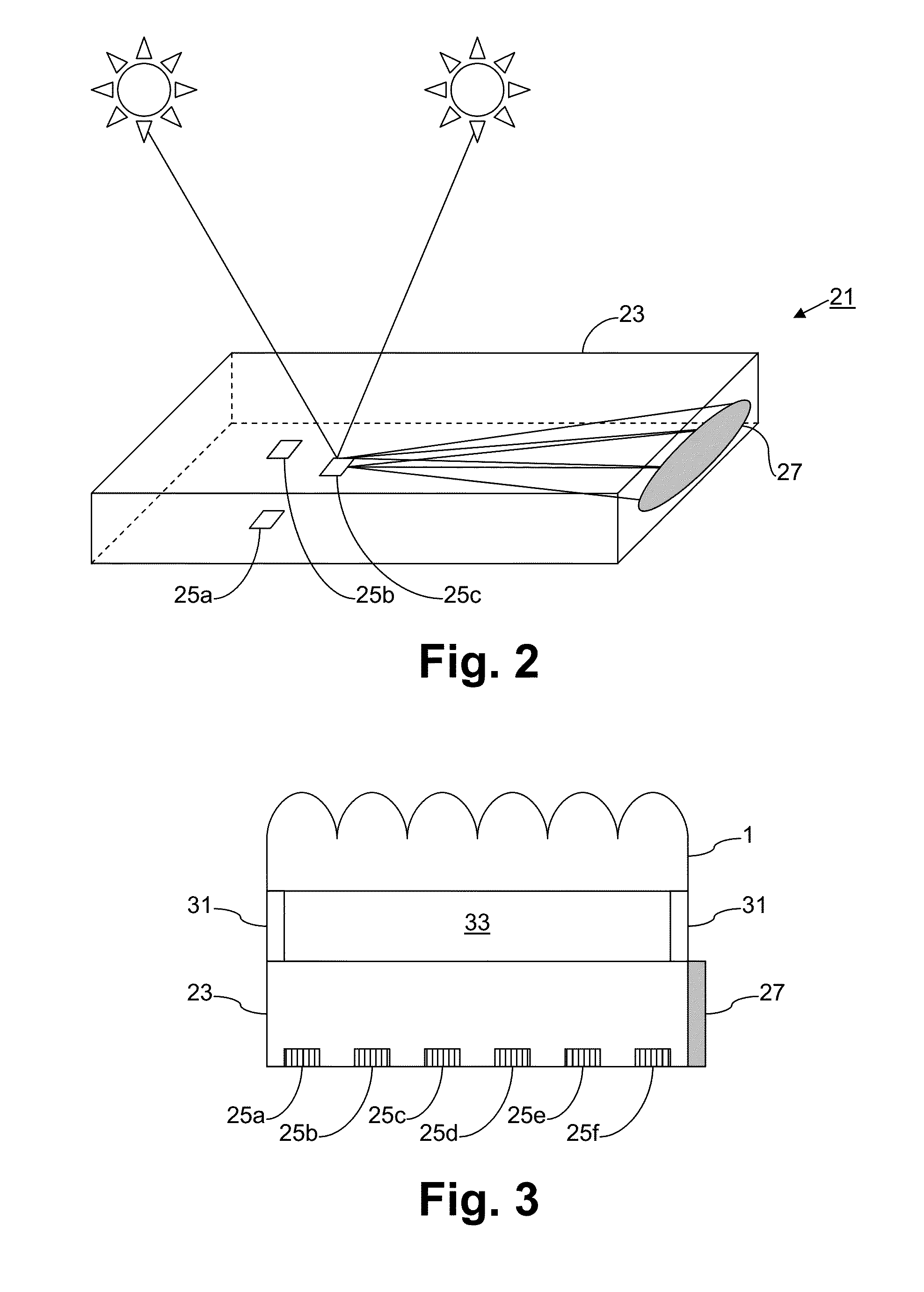
[0020]Certain example embodiments relate to an alternative approach for planar concentration by replacing multiple non-imaging secondary optics and their associated photovoltaic (PV) cells with a single multimode glass waveguide connected to a shared PV cell. Sunlight collected by each aperture of the arrayed primary optical element may, for example, be coupled into a common glass slab waveguide using spatially localized re-directing features such as holograms, prisms, gratings on surface 2, scattering features in the bulk of the glass waveguide, and / or the like.

[0021]In certain example embodiments, once scattered or diffracted, incoming rays that exceed the critical angle defined by Snell's Law propagate via total internal reflection (TIR) within the waveguide to the exit aperture, which may in certain example embodiments be provided at the edge of the slab. Because TIR is a complete reflection with negligible spectral or polarization-dependent losses, this arrangement advantageous...


PUM


Abstract

Improved building-integrated photovoltaic (BIPV) systems according to certain example embodiments may include concentrated photovoltaic skylights or other windows in which holographic optical elements (HOEs) are provided. The HOEs are formed on or in a substantially planar glass substrate, e.g., at light coupling locations, and they help form a holographic projection of light in a desired wavelength range on a photovoltaic module. The photovoltaic module may, for example, be connected to an outer edge of the substrate in certain example embodiments. Holographically projected light may propagate through the substrate in accordance with the principles of total internal reflection (TIR), which may be somewhat lossy in some cases. A lens provided between the light source (e.g., the sun) may help re-orient the light in a desired direction so as to improve the efficiency of the HOEs.

Description

FIELD OF THE INVENTION[0001]Certain example embodiments of this invention relate to improved solar photovoltaic systems for use in building-integrated photovoltaic applications, and / or methods of making the same. More particularly, certain example embodiments of this invention relate to building-integrated photovoltaic systems including concentrating photovoltaic skylights or other windows based on holograms, and / or methods of making the same.BACKGROUND AND SUMMARY OF EXAMPLE EMBODIMENTS OF THE INVENTION[0002]Photovoltaic devices such as solar cells convert solar radiation into usable electrical energy. The energy conversion occurs typically as the result of the photovoltaic effect. Solar radiation (e.g., sunlight) impinging on a photovoltaic device and absorbed by an active region of semiconductor material generates electron-hole pairs in the active region.[0003]Photovoltaic devices are known in the art (e.g., see U.S. Pat. Nos. 6,784,361, 6,288,325, 6,613,603, and 6,123,824, the d...

Claims


Application Information

Patent Timeline
IPC IPC(8): H01L31/054G03H1/02H02S20/26
CPCH01L31/054G03H1/0272H02S20/26G02B5/32G03H1/0248G03H2001/0268G03H2001/2226H01L31/0543H01L31/0547H01L31/0549Y02A30/60Y02B10/10Y02E10/52
Inventor BRACAMONTE, MARTIN D.VEERASAMY, VIJAYEN S.
Owner GUARDIAN GLASS LLC
Why Eureka
Try Eureka