Electrospark deposition process for oxidation resistant coating of cooling hole

a technology of oxidation resistance coating and electrochemical deposition, which is applied in the direction of machines/engines, manufacturing tools, light and heating equipment, etc., can solve the problems of no process to prevent crack initiation at the aft end cracks or fractures around the cooling hole located on the frame, and no process to prevent crack initiation of the cooling hole, etc., to improve the resistance to oxidation of the substrate metal, reduce the number of turbine components, and increase the number of turbin

Inactive Publication Date: 2016-02-04
GENERAL ELECTRIC CO
View PDF3 Cites 3 Cited by
  • Summary
  • Abstract
  • Description
  • Claims
  • Application Information

AI Technical Summary

Benefits of technology

[0008]The present disclosure includes a method to enhance the oxidation resistance of the cooling hole exit locally by applying an ESD process with the electrode having an appropriate tip profile. The ESD process establishes an electrospark between the rotary electrode and the hole exit. Heat from the electrospark deposition softens and deforms the upper corner of the cooling hole to form a rounded edge with an alloy coating that provides improved resistance to oxidation of the substrate metal.
[0009]An advantage of the disclosed method is a reduction in the number of turbine components discarded or scrapped.
[0011]Still another aspect of the disclosure is the ability to build up an ESD coating layer having a superior resistance to oxidation of the metal substrate.

Problems solved by technology

Under the high temperature operating conditions of the gas turbine engine, fracture or cracks may occur around the cooling holes located on portions of the frame.
Failure analysis has revealed that such cracks form perpendicular to the inner surface of the frame, which indicates that thermal stresses played a role in forming the cracks occurring at the cooling hole.
Grain boundary oxidation and thermal fatigue are potential causes of such cracking.
Analysis indicated that cracks in the cooling holes of the frame followed the oxidized grain boundaries.
Currently there is no process to prevent crack initiation at the aft end of the cooling holes.

Method used


Image

  • Electrospark deposition process for oxidation resistant coating of cooling hole
  • Electrospark deposition process for oxidation resistant coating of cooling hole
  • Electrospark deposition process for oxidation resistant coating of cooling hole

Examples


Embodiment Construction

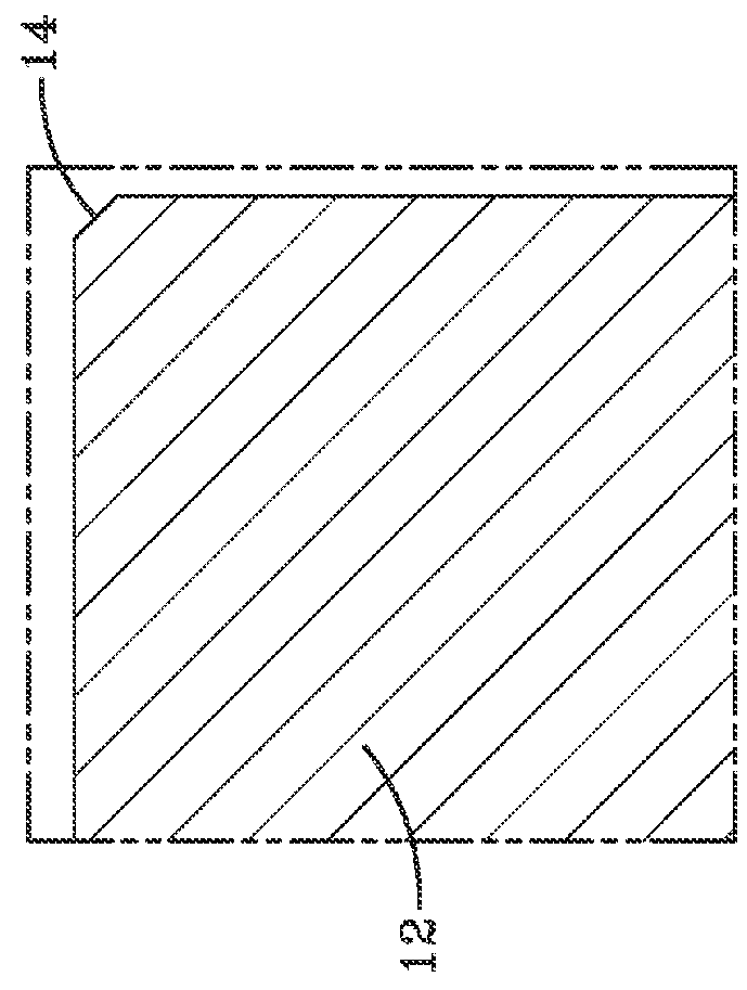
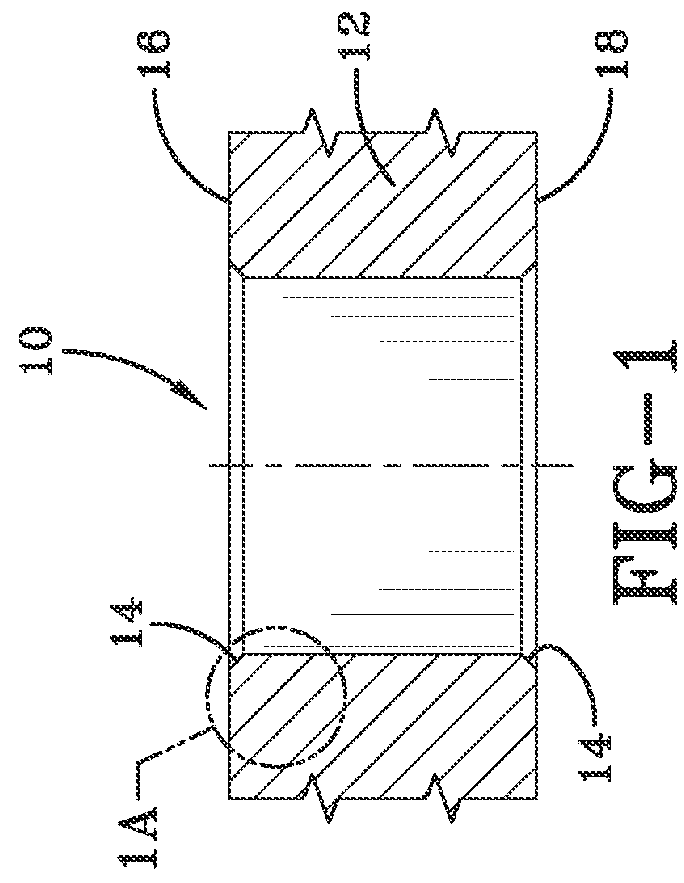
[0022]Referring to FIG. 1 and FIG. 1a are a cross-sectional view of a prior art cooling hole is shown. A cooling hole 10 passes through a metal frame substrate 12. An edge 14 of the cooling hole 10 appears at each of the top surface 16 or the bottom surface 18 of metal frame substrate 12. Cooling hole 10 is formed in metal frame substrate 12 to provide air flow therethrough for cooling metal substrate 12 in harsh, high temperature environments, e.g., in a gas turbine engine transition piece (not shown). Edges 14 are subject to oxidation when exposed to harsh, high temperature environments such as are present in a gas turbine engine. The oxidized substrate material adjacent to cooling holes 10 results in cracks forming in metal substrate 12 around cooling holes 10. In particular, at the aft-facing side end of metal substrate 12 cracks are prone to form.

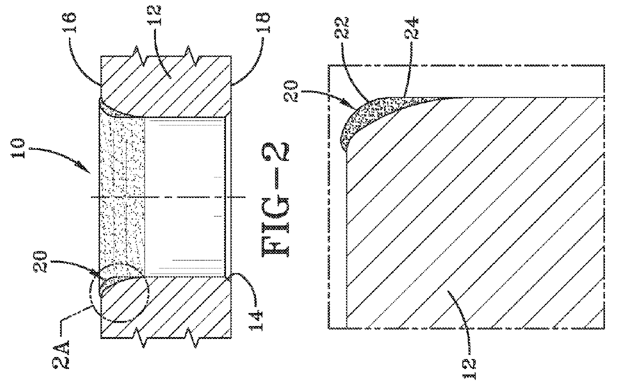
[0023]Referring next to FIGS. 2 and 2A, a cooling hole 10 is shown which has been treated by the ESD coating process described in gre...


PUM

PropertyMeasurementUnit
thicknessaaaaaaaaaa
thickaaaaaaaaaa
thicknessaaaaaaaaaa

Abstract

A method of providing an oxidation resistant coating is disclosed. The method includes providing a substrate having a first surface and cooling holes. A portable coating device includes electro-spark deposition (ESD) equipment and an ESD torch connected with the ESD equipment. The ESD torch has an inert gas source and a rotary electrode conductive material. The rotary electrode is positioned within the ESD torch, and is shielded by an inert gas. The rotary electrode applies a compositionally controlled protective coating to the first surface of the substrate. Then the rotary electrode is inserted into the cooling hole and generates an electrospark between rotary ESD electrode and the substrate to form a rounded edge and deposit a coating of electrode material alloy at a cooling hole edge.

Description

FIELD OF THE INVENTION[0001]This application generally relates to gas turbine components. The application relates more specifically to the use of an electrospark deposition process to apply an oxidation resistant coating to a cooling hole of a gas turbine component.BACKGROUND OF THE INVENTION[0002]Many component parts of a gas turbine engine include cooling holes for active cooling of engine sections located downstream of the turbine section. The rising combustor exit temperatures in gas turbine engines necessitate active cooling to avoid thermal failure. For example, a transition piece for a gas turbine engine typically includes an integral frame portion surrounding an opening at a downstream end where the transition piece connects to the turbine stage. An exemplary transition piece is described in U.S. Pat. No. 5,414,999.[0003]Under the high temperature operating conditions of the gas turbine engine, fracture or cracks may occur around the cooling holes located on portions of the ...

Claims


Application Information

Patent Timeline
Patent Type & Authority Applications(United States)
IPC IPC(8): B23K9/04F01D5/18
CPCF01D5/185B23K9/04F01D9/023F05D2230/90F05D2260/202C23C26/02Y10T428/12361
Inventor LIN, DECHAOUCOK, IBRAHIMONAL, KIVILCIM
Owner GENERAL ELECTRIC CO
Why Eureka
Try Eureka