Nitride phosphor and method for producing the same

Active Publication Date: 2016-02-11
MITSUBISHI CHEM CORP
View PDF0 Cites 11 Cited by
  • Summary
  • Abstract
  • Description
  • Claims
  • Application Information

AI Technical Summary

Benefits of technology

[0029]The present invention enables providing a nitride phosphor of improved emission luminance, specifically a nitride phosphor having improved emission peak intensity, and a liq

Problems solved by technology

However, there are problems associated with the YAG phosphor.
One problem is that temperature quenching, a phenomenon in which luminance decreases with increase in phosphor temperature, becomes high under high output conditions.
Another problem is that luminance seriously degrades when the YAG

Method used


Image

  • Nitride phosphor and method for producing the same
  • Nitride phosphor and method for producing the same
  • Nitride phosphor and method for producing the same

Examples


Example

Example 1

[0185]Source materials were prepared in a nitrogen-filled glove box, using LaN, Si3N4 (Ube Industries SN-E10), and CeF3 (Pure Chemical Co., Ltd.) in the starting composition ratio shown in Table 1. Specifically, LaN (17.67 g), Si3N4 (10.81 g), and CeF3 (1.52 g) were weighed, and thoroughly mixed on an alumina mortar. An about 3-g portion from the mixture was then charged into a molybdenum crucible.

[0186]For first sintering, the crucible was placed in a resistance heating electric furnace equipped with a temperature adjuster, and heated in the atmospheric pressure under a stream of a mixed gas (96 volume % nitrogen, 4 volume % hydrogen) supplied at 2 liters / min. The rate of temperature increase was 5° C. / min from room temperature to 1200° C., and 1° C. / min from 1200° C. to 1250° C. The sample was maintained for 4 hours, and allowed to cool to room temperature.

[0187]The sample was then transferred to the nitrogen-filled glove box, and sieved into sizes of 100 μm or less. The ...

Example

Example 2

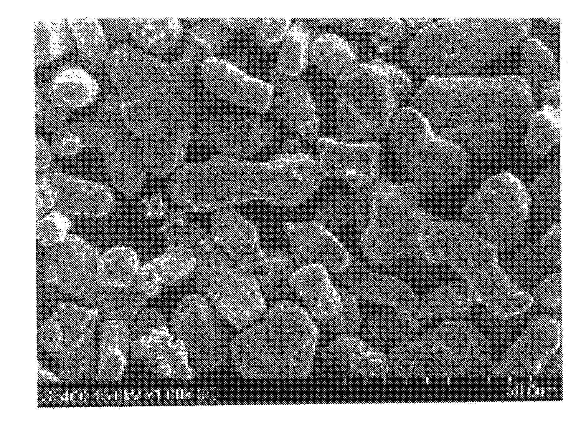
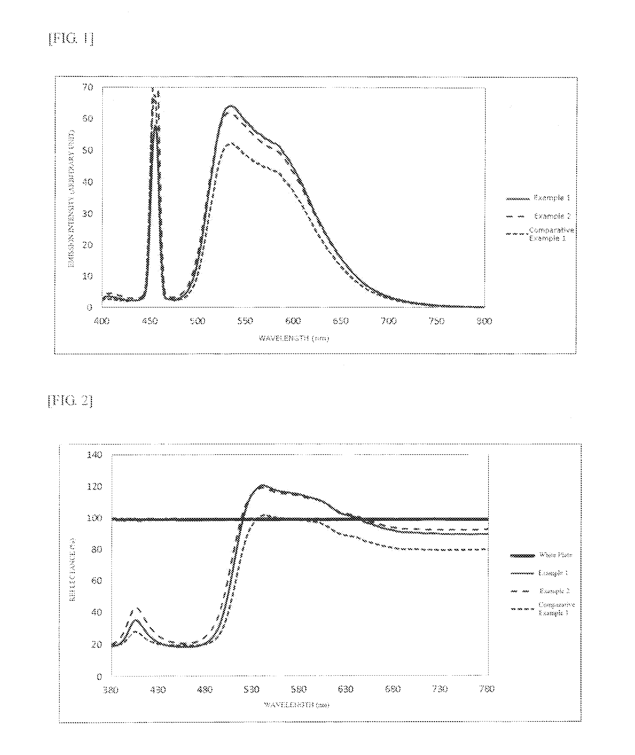
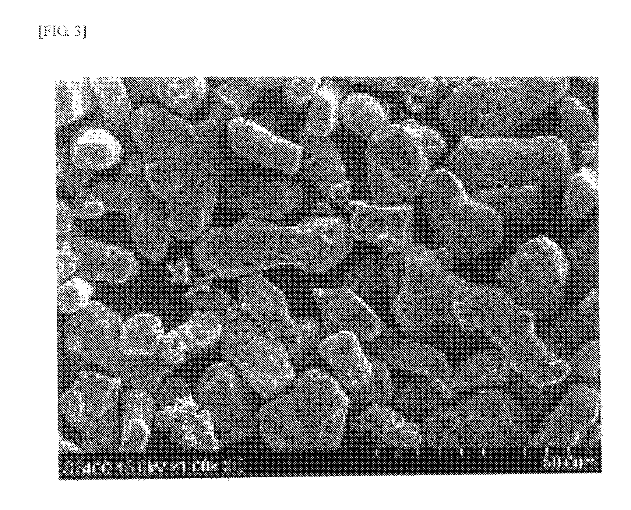
[0189]A phosphor synthesis was performed in the same manner as in Example 1, except that the retention temperature for first sintering was changed from 1250° C. to 1300° C. The result of the characteristic evaluation of the phosphor is presented in Table 2. FIG. 1 shows the emission spectrum, FIG. 2 shows the reflection spectrum (A), and FIG. 4 shows a SEM image. The emission peak intensity was 62 upon excitation at 455 nm. The evaluation also revealed that reflectance Ra was 92% at 770 nm wavelength.

Example

Comparative Example 1

[0190]A phosphor synthesis was performed in the same manner as in Example 1, except that only the primary sintering was performed without first sintering.

[0191]The result of the characteristic evaluation of the phosphor is presented in Table 2. FIG. 1 shows the emission spectrum, FIG. 2 shows the reflection spectrum (A), and FIG. 5 shows a SEM image. The emission peak intensity was 52 upon excitation at 455 nm. The evaluation also revealed that reflectance Ra was 80% at 770 nm wavelength. It was found from these results that LSN phosphors of high reflectance and high emission peak intensity can be obtained when the phosphor is sieved and sintered again after the first sintering.

[0192]In regard to conventional LSN phosphors, it is known that the 135 phosphor generates in increased amounts in the presence of oxygen in the source material or in the atmosphere. This raised concerns that oxygen might become mixed with the phosphor upon taking the phosphor out of the ...


PUM


Abstract

The present invention related to a nitride phosphor represented by the following general formula (1), the nitride phosphor having an x value of less than 0.43 in luminescent color coordinates (x, y) upon being excited with excitation light of 455 nm, and a reflectance Ra of 89% or more at 770 nm;
LnxSiyNn:Z  (1),
wherein Ln is a rare-earth element excluding the element used as an activator, Z is an activator, x satisfies 2.7≦x≦3.3, y satisfies 5.4≦y≦6.6, and n satisfies 10≦n≦12.

Description

TECHNICAL FIELD[0001]The present invention relates to a nitride phosphor, a liquid medium containing the nitride phosphor, a light-emitting unit that includes the nitride phosphor, and a lighting device that includes the light-emitting unit.BACKGROUND ART[0002]With the recent trend for energy saving, there is an increasing demand for lightings and backlights that use LEDs. The LEDs used for these applications are white emitting LEDs of a construction in which a phosphor is disposed on an LED chip that emits light of blue or near ultraviolet wavelengths. Many of such white emitting LEDs use a YAG (yttrium-aluminum-garnet) phosphor that emits a yellow color by using the blue excitation light from a blue LED chip disposed underneath the YAG phosphor.[0003]However, there are problems associated with the YAG phosphor. One problem is that temperature quenching, a phenomenon in which luminance decreases with increase in phosphor temperature, becomes high under high output conditions. Anoth...

Claims


Application Information

Patent Timeline
IPC IPC(8): C09K11/77H01L33/50
CPCC09K11/7774H01L33/507H01L33/502C09K11/0883C09K11/7715C09K11/7728H01L2224/48091H01L2924/181H01L2224/48247F21K9/64C09K11/77747H01L2924/00012
Inventor SHIMOOKA, SATOSHIOHTO, AKIHIROTAKASHINA, SHIHO
Owner MITSUBISHI CHEM CORP
Why Eureka
Try Eureka