Smoke and/or Vapor Ignition, Cooling and Dispensing Device

a technology of vapor ignition and smoke, which is applied in the field of therapeutic smoking and/or vaporizing devices, can solve the problems of inability to portability external active cooling, limited use time, and active smoke cooling

Inactive Publication Date: 2016-02-18
OCONNOR GEORGE PATRICK
View PDF3 Cites 29 Cited by
  • Summary
  • Abstract
  • Description
  • Claims
  • Application Information

AI Technical Summary

Benefits of technology

[0011]Next, being that the air, smoke and / or vapor stream has been cooled, its density has also preferably increased as a result, and therefore causes the air, smoke and / or vapor stream to flow with properties similar to that of a liquid. This makes it possible to allow the air, smoke / vapor stream to flow from the Dispensing Nozzle and into a Serving Means while it sinks to the bottom and therefore fills the Serving Means from bottom up. The chilled air, smoke and / or vapor can then easily be poured out again from the Serving Means, like a liquid, to be ingested or consumed by the user.
[0012]In a preferred embodiment, the method of providing low temperatures to the Cold Block (FIG. 15) is obtained by providing electric power to a Thermo electric Generator (FIG. 21). As electric power is supplied to the Thermo electric Generator (FIG. 21), one side begins to turn cold while heat is transferred to other side, and therefore begins to turn hot. To help draw heat away from the hot side and thus helping to create further cooling by maintaining a maximum temperature differential between the hot side and cold side of the Thermo electric Generator (FIG. 21), a secondary block (Liquid Coolant Block (FIG. 20)) with a maze of liquid coolant channels is positioned against the hot side of the Thermo electric Generator (FIG. 21) acting as a heat sink.
[0014]After the liquid coolant is passed through the Liquid Coolant Block (FIG. 20) while drawing heat away by thermal transfer, it exits back out through the Liquid Coolant Block Face Plate (FIG. 22) via a third length of Hose and into a Radiator (FIG. 25B). As the liquid coolant passes through the Radiator (FIG. 25B), an electrically powered Fan (FIG. 27) is positioned along side of the Radiator (FIG. 25B) in order to blow the collected heat away from and out of the system, therefore decreasing the temperature of the liquid coolant. The radiated / cooled liquid then exits the Radiator (FIG. 25B) returns back to the Liquid Coolant Reservoir (FIG. 24) via a fourth Length Hose to be used again in this liquid cooling system.

Problems solved by technology

Some combinations have employed the use of a passive means of chilling the smoke stream while utilizing a solid-phase cooling medium that connects to or surrounds the smoke stream stem on its way to the user in order for tempering and treating smoke such as in U.S. Pat. No. 4,164,950 A. The main limitation of U.S. Pat. No. 4,164,950 A, being the need for an external active cooling means such as a freezer to arrive at desired temperatures, the non-ease for portability of the external active cooling means, and the limitations of length of time of use and also between uses, since once the passive cooling means has absorbed the ambient temperatures of the surrounding environment, the means to cool the smoke ceases.
Similar limitations are present in U.S. Pat. No. 2,827,903 A, whereas the means for cooling the smoke as it passes to the user employs the use of heat fins as a passive heat exchanger in order to dissipate heat away from the smoke stream and into the ambient surrounding temperatures and atmosphere by use of metal fins as heat sinks.
Some limitations being that the cooling means depends on the ambient temperatures of the environment in which it is being used, as well as the size and efficiency of the heat fins themselves since they are acting again here, as passive heat exchangers.
There have been past descriptions of devices which do suggest the use of an active cooling means to cool a thermal mass prior to smoking, so as to cool the gaseous flow of smoke prior to reaching the consumer as they inhale the smoke stream, such as in published international application WO 2012079887 A1, The drawback to this description being that it is in a configuration that does not actively cool the smoke and / or vapor continuously while it is being produced and consumed.
While this seems to be one possible way to obtain a cooled smoke stream, the author also describes some of its limitations, that being, as the cigarette is being smoked, the heat coming from the burning end of the cigarette is increasingly being absorbed by the cooled thermal mass, in this case being the cigarette filter, without the means to keep the device cold for the full duration of use as in published international application WO 2012079887 A1.
This system is also limited by ambient environmental temperatures and does not allow for the cigarette to be put out for later use without the thermal mass or filter losing its coolness.
Obvious drawbacks to this configuration as well as those indicated by the inventor, are the lack of heat dissipation within the overall system (pipe), which because of its limitations could potentially cause overheating, and therefore, ultimately overcome any gain of the cooling effects of the second Peltier element due to the simple natures of thermal transfer and conduction within a closed system.
The prolonged use and / or time between uses of said device could become limited for the exact same reasons.
The overall temperature of the system lacks the means of actively remove heat away from the appliance and therefore likely may not be used continuously and has the potential to easily overheat.
The author describes some of these potential problems with the overall heat collected in the device and suggests the use of an external refrigeration unit to draw off excess heat in some cases as a solution, which is not always a readily available nor convenient option for the users of the device.

Method used


Image

  • Smoke and/or Vapor Ignition, Cooling and Dispensing Device
  • Smoke and/or Vapor Ignition, Cooling and Dispensing Device
  • Smoke and/or Vapor Ignition, Cooling and Dispensing Device

Examples


Embodiment Construction

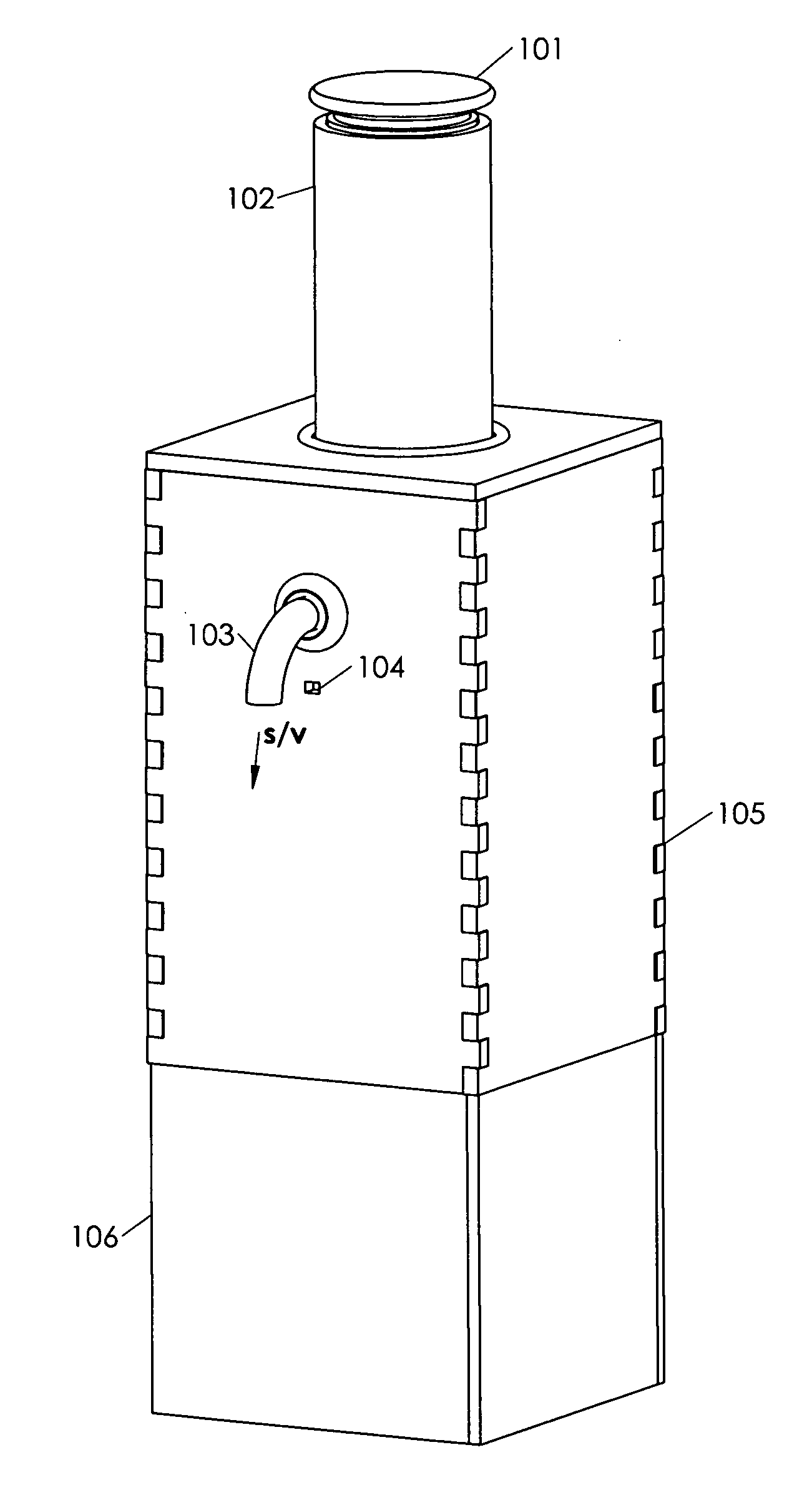
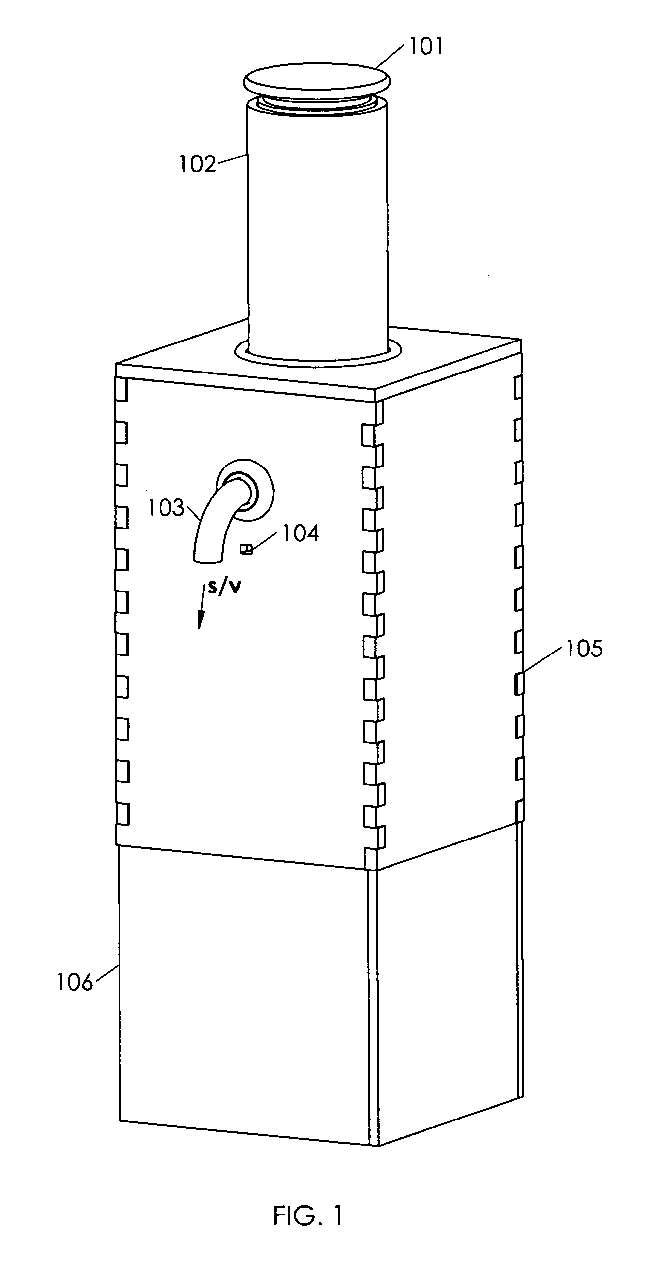
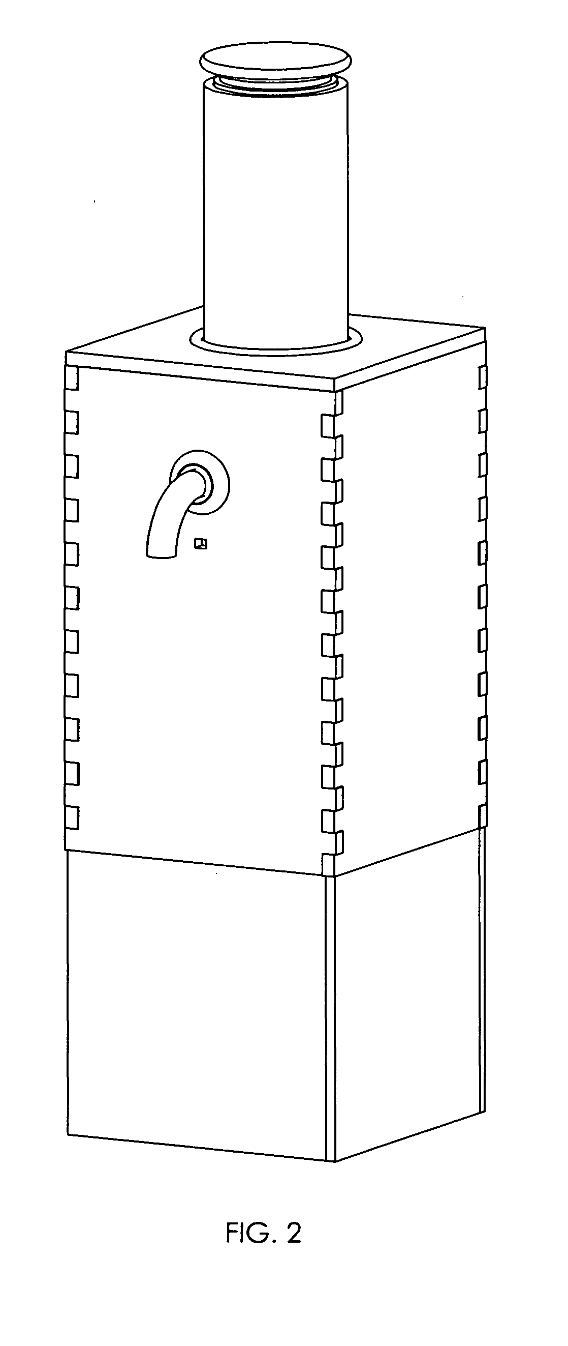
[0009]The preferred embodiment described here begins by the user placing the Material to be Combusted and / or Vaporized into the Bowl (FIG. 7). Next, a Plenum Chamber (FIG. 10) is placed over the Bowl (FIG. 7) creating an air tight chamber to be pressurized, while the Bowl (FIG. 7) provides a passage for any positive pressure of air, liquid, or gas to pass through. After filling the Bowl (FIG. 7) with the desired material and creating an air-tight seal by placing the Plenum Chamber (FIG. 10) in its position, power is then provided to the Heating Element (FIG. 8) by the user activating a switch or sensor switch. The Heating Element (FIG. 8) then reaches temperatures in sufficiency to cause combustion, and / or vaporization while coming into contact and / or near proximity with the Material to Combusted and / or Vaporized. In a preferred embodiment, this occurs simultaneous to the Air Pump (FIG. 29) providing a supply of air to the Plenum Chamber (FIG. 10) via a Length of Tubing as electric ...


PUM


Abstract

A device which generates, cools and dispenses smoke and / or vapor intended for therapeutic use as well as recreational and flavor enjoyment providing ease of control and operation of said device, while heating the desired herb or essential oil enough to be combusted and / or vaporized, then subsequently chilled before being dispensed to the user by air stream. It also provides additional possible benefits such as filtration of condensed tars from cooled smoke, and possible decreased respiratory irritation. In one preferred embodiment, the device may be constructed as a single simple and portable home use unit. In another preferred embodiment, a single or multiple channeled commercial dispensing unit for use on many commercial levels of application. It may be used with materials such as different types of tobacco and / or herbs such as lavender, chamomile, peppermint, cannabis indica, cannabis sativa, with the different strains or phenotypes of each accentuated, as well as the essential oils and / or extracts of said herbs.

Description

CROSS REFERENCE TO RELATED APPLICATIONS[0001]This application is a non-provisional application claiming the benefits of provisional application No. 61 / 853,916 filed Apr. 15, 2013.FIELD OF INVENTION[0002]This invention relates to a therapeutic smoking and / or vaporizing device used for smoking and / or vaporizing material to be smoked and / or vaporized through an appliance that both actively heats up the smoking and / or vaporizing material to ignition temperatures, and then subsequently also chills or cools down the smoke and / or vapor stream before being dispensed from said appliance in order to maximize the full therapeutic experience, while also minimizing throat and lung irritation due to low temperature delivery of smoke and / or vapor to the consumer.BACKGROUND OF INVENTION[0003]Many people enjoy smoking and / or vaporizing various items such as tobacco, herbs, and essential oils, and desire the smoke and / or vapor to be cooled before consumption. There are several methods currently used ...

Claims


Application Information

Patent Timeline
Patent Type & Authority Applications(United States)
IPC IPC(8): A24F1/00A24F40/20A24F40/48
CPCA24F1/00A24F47/008A24F40/48A24F40/20
Inventor O'CONNOR, GEORGE, PATRICK
Owner OCONNOR GEORGE PATRICK
Why Eureka
Try Eureka